This post will expand the general virtual work equation to consider deflections due to flexural strains.

Deriving Virtual Work Due to Flexural Strains
Let's expand on the general virtual work expression derived earlier to consider deflection under flexural strains. Ultimately, we can derive the equations used to compute flexural deflections.
WeTheStudy lets you connect ideas
Learn moreWant to access the remaining content?
You're a Member!
Click to expand on exclusive content
Want to access the remaining content?

Complete Your Checkout
When you complete your account, here are the following benefits:
PROCEED CHECKOUT
Let's continue exploring the simple beam we encountered while discussing the general virtual work equation. Our goal here is to find \(U_{s_\delta}\) so that we can arrive at a definite expression to solve for the deflection of flexural structures.
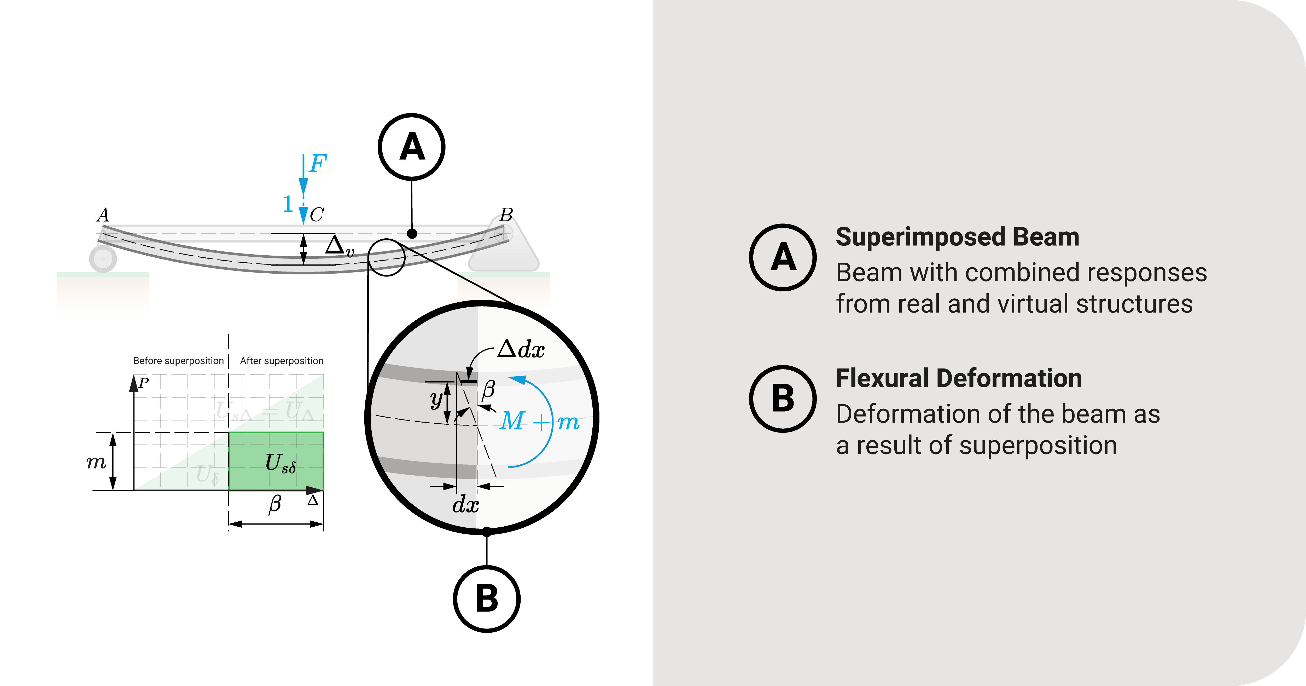
Again, \(U_{s_\delta}\) is the area, as shown in the figure. Symbolically, we can express it as:
Equation 1: \(U_{s_\delta}=\int{m}d\beta\)
- The variable \(m\) refers to the fictional internal force of the beam or frame; In this case, it would be the bending moment equations (as a function of \(x\)) of the virtual structure, as also seen in the figure.
- The variable \(d\beta\) refers to the flexural strain caused by the superimposition of loads.
The variable \(m\) is pretty straightforward, but \(d\beta\) requires further derivation.
Let's consider a section of the superimposed beam, as seen in the figure. As loads are applied, the fibers of the structure will deform. We can express this minuscule deformation as \(d\beta\), and is equal to:
Equation 2: \(\tan{d\beta}=d\beta=\frac{\Delta{dx}}{y}\)
As much as Equation 2 is our first step in describing \(d\beta\). It doesn't give us much detail; hence, we use constitutive relationships to expand it further.
Because we have assumed that the superimposed structure is still in the elastic region, there is a relationship among stress \(f\), strain \(\epsilon\), and modulus of elasticity \(E\) as any Strength of Materials course will tell you:
Equation 3: \(f=E\epsilon\)
Since we are concerned with flexural structures, we can express \(f\) as defined by the flexural stress formula:
Equation 4: \(f=\frac{My}{I}\)
Furthermore, we remember that strain is the ratio of change in length to its original size. In our section, this is:
Equation 5: \(\epsilon=\frac{\Delta{dx}}{dx}\)
From Equations 3 to 5, we can derive a specific relationship that would help us develop Equation 2:
\(\frac{My}{I}=E\epsilon\)
\(\frac{My}{I}=E\times\frac{\Delta{dx}}{dx}\)
Equation 6: \(\frac{\Delta{dx}}{y}=\frac{M}{EI}dx\)
Notice we can equate Equations 2 and 6 to arrive at the following:
Equation 7: \(d\beta=\frac{M}{EI}dx\)
We substitute Equation 7 to 1 to determine \(U_{s_\delta}\):
Virtual Work - Flexural Strain Energy: \(U_{s_\delta}=\int\frac{Mm}{EI}dx\)
This equation is the flexural strain energy expression we will use in solving deflection components.
Graphical Interpretation
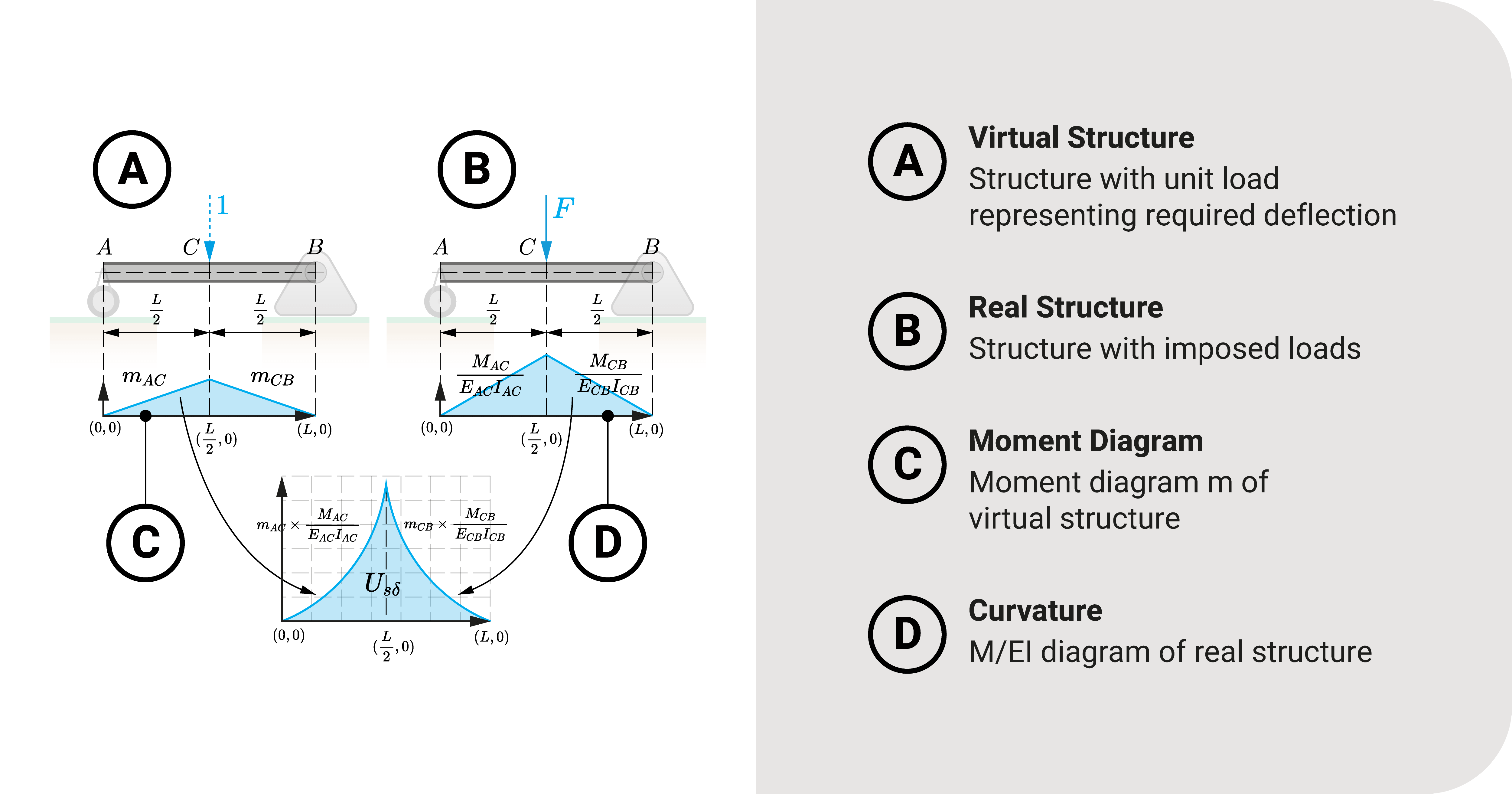
Another way of interpreting this equation is through the following figure, which shows a graphical perspective. The left structure is our virtual beam with its moment diagram, while the right is the superimposed beam with its \(\frac{M}{EI}\) diagram. Strain energy is the area of the product of these two graphs.
Key Idea: Virtual Work Due to Flexural Strains
Now that we have solved for \(U_{s_\delta}\), let's equate it back to the general virtual work equation:
Virtual Work - Flexural Strains - Horizontal Translation: \(1{\times}\Delta_h=\int_{x_1}^{x_2}\frac{Mm_h}{EI}dx\)
Virtual Work - Flexural Strains - Vertical Translation: \(1{\times}\Delta_v=\int_{x_1}^{x_2}\frac{Mm_v}{EI}dx\)
Virtual Work - Flexural Strains - Rotation: \(1{\times}\theta=\int_{x_1}^{x_2}\frac{Mm_\alpha}{EI}dx\)
Here is the meaning of the variables in those equations:
- The unit force or couple represents the fictional unit load applied to the virtual structure.
- \(\Delta\) (or \(\theta\)) describe the components we would like to investigate.
- \(M\) is the bending moment equation caused by real loadings (usually a function of position \(x\))
- \(m_v\), \(m_h\), \(m_\alpha\) are the bending moment equations caused by the unit loading of the virtual structure.
- \(EI\) is flexural rigidity.
- Limits \(x_1\) and \(x_2\) are the member's local start and end coordinates, respectively.
These equations are the expressions we will use to solve for flexural deflection in structures such as beams or frames. Later on, we'll use a beam example on how to apply this set of equations to solve for translation and rotation.
Summary
Let's summarize:
The expression for the superimposed fictional strain energy due to flexural strains is \(U_{s_\delta}=\int\frac{Mm}{EI}dx\).
It is the area of the product of two graphs: the virtual beam with its moment diagram and the superimposed beam with its \(\frac{M}{EI}\) diagram.
The equations we will use to solve for the deflections are the following: (1) \(1{\times}\Delta_h=\int_{x_1}^{x_2}\frac{Mm_h}{EI}dx\), (2) \(1{\times}\Delta_v=\int_{x_1}^{x_2}\frac{Mm_v}{EI}dx\), and (3) \(1{\times}\theta=\int_{x_1}^{x_2}\frac{Mm_\alpha}{EI}dx\).
Tree Navigation
See how this article relates to other ideas
Children
No children (yet)


Connections
No connections (yet)
Created On
June 5, 2023
Updated On
February 23, 2024
Contributors
Edgar Christian Dirige
Founder
References
WeTheStudy original content
Revision
1.00
Got some questions? Something wrong? Contact us