How to Use Partial Derivative Method Due to Axial Strains?
Let's illustrate how to solve the deflections of trusses using the partial derivative method. We shall demonstrate how to solve the rotation of a truss member.
The solution presented is in SI. The author will update the post soon to reflect English units.
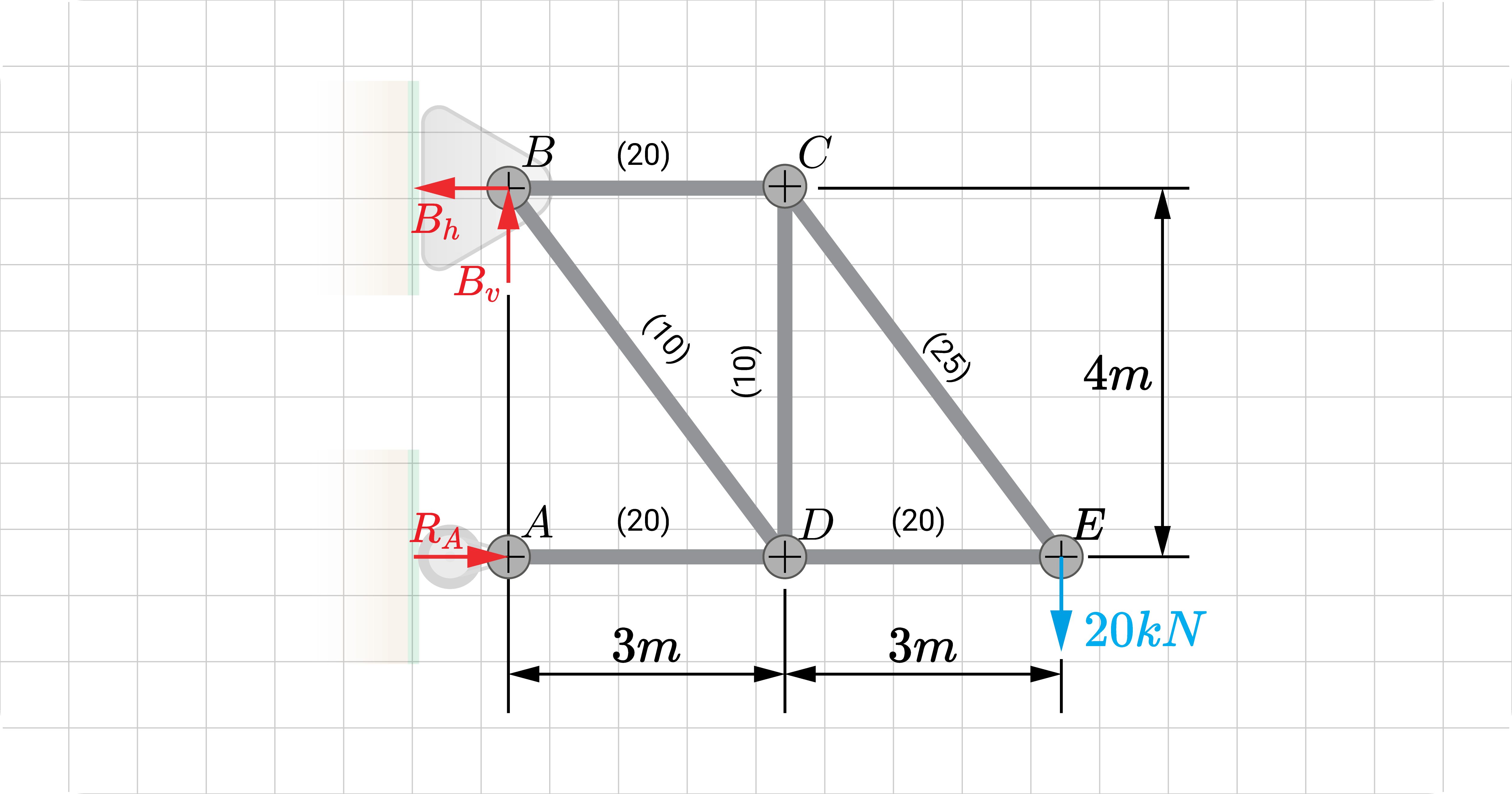
To start, we shall consider a simple truss. It has a \(20 kN\) point load at \(E\). The value inside the parenthesis () is the member's cross-sectional area \(A\) in square centimeters.
Say that we are interested in finding the rotation of member \(CE\). We solve it using the partial derivative method.
For this problem, we'll assume that all members are made of the same material so that the modulus of elasticity \(E\) is constant.
Main Solution
Want to access the remaining content?
You're a Member!
Click to expand on exclusive content
Want to access the remaining content?
Become a Member
When you sign-up and subscribe to WeTheStudy, you’ll get the following benefits:
The first step is introducing a placeholder couple \(M_P\) on member \(DE\). It represents the rotation of said member - the thing we want to solve. We apply a pair of equal and parallel forces at the ends of member \(DE\). We'll assume that the rotation of the member is clockwise; hence, the effect of these two forces should be the same.
Formulate S, A, and E Equations
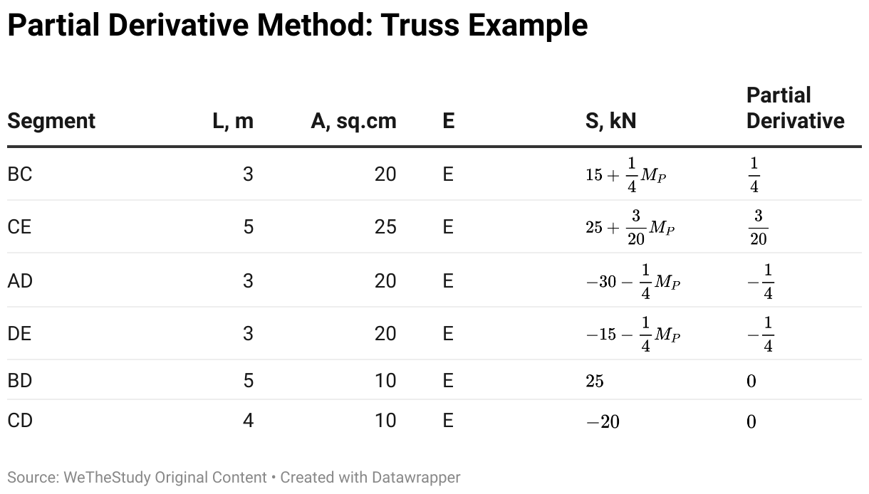
With a placeholder introduced, we formulate axial equations \(S\), \(A\), and \(E\) based on the real and placeholder loads.
The following table shows the summary of each variable per member.
Apply Partial Derivative Equations
At this point, we apply the partial derivative method to solve for member rotation \(CE\).
As the name suggests, we need to find the partial derivative of the axial equation with respect to the placeholder load:
Member BC
\(\frac{\partial S}{\partial M_P}=\frac{1}{4}\)
Member CE
\(\frac{\partial S}{\partial M_P}=\frac{3}{20}\)
Member AD
\(\frac{\partial S}{\partial M_P}=-\frac{1}{4}\)
Member DE
\(\frac{\partial S}{\partial M_P}=-\frac{1}{4}\)
Member BD
\(\frac{\partial S}{\partial M_P}=0\)
Member CD
\(\frac{\partial S}{\partial M_P}=0\)
Afterward, we apply the partial derivative equation to solve for the rotation:
\(\theta_{C E}=\int \frac{S}{A E} \times \frac{\partial S}{\partial M_P} d x\)
\(\theta_{C E}=\frac{1}{(20)(E)} \int_0^3\left(15+\frac{1}{4} M_P\right)\left(\frac{1}{4}\right) d x+\frac{1}{(25)(E)} \int_0^5\left(25+\frac{3}{20} M_P\right)\left(\frac{3}{20}\right) d x\)
\(+\frac{1}{(20)(E)} \int_0^3\left(-30-\frac{1}{4} M_P\right)\left(-\frac{1}{4}\right) d x+\frac{1}{(20)(E)} \int_0^3\left(-15-\frac{1}{4} M_P\right)\left(-\frac{1}{4}\right) d x+\frac{1}{(10)(E)} \int_0^5(25)(0) d x\)
\(+\frac{1}{(10)(E)} \int_0^4(-20)(0) d x\)
Notice that the rotation of \(CE\) is in terms of two variables: the placeholder load \(M_P\) and \(x\). We cannot directly evaluate the integral because of it; however, we recall that the purpose of \(M_P\) is to represent the required deflection. So, we let \(M_P = 0\) to have:
\(\theta_{C E}=\frac{1}{(20)(E)} \int_0^3(15)\left(\frac{1}{4}\right) d x+\frac{1}{(25)(E)} \int_0^5(25)\left(\frac{3}{20}\right) d x+\frac{1}{(20)(E)} \int_0^3(-30)\left(-\frac{1}{4}\right) d x\)
\(+\frac{1}{(20)(E)} \int_0^3(-15)\left(-\frac{1}{4}\right) d x+\frac{1}{(10)(E)} \int_0^5(25)(0) d x+\frac{1}{(10)(E)} \int_0^4(-20)(0) d x\)
\(\theta_{C E}=\frac{3}{E}\)
The positive sign indicates that member \(CE\) indeed rotated clockwise from its original position.