Let's illustrate how to solve the deflections of trusses using the virtual work method. We shall demonstrate how to solve the movement of a truss joint and the rotation of a member.
The solution presented is in SI. The author will update the post soon to reflect English units.
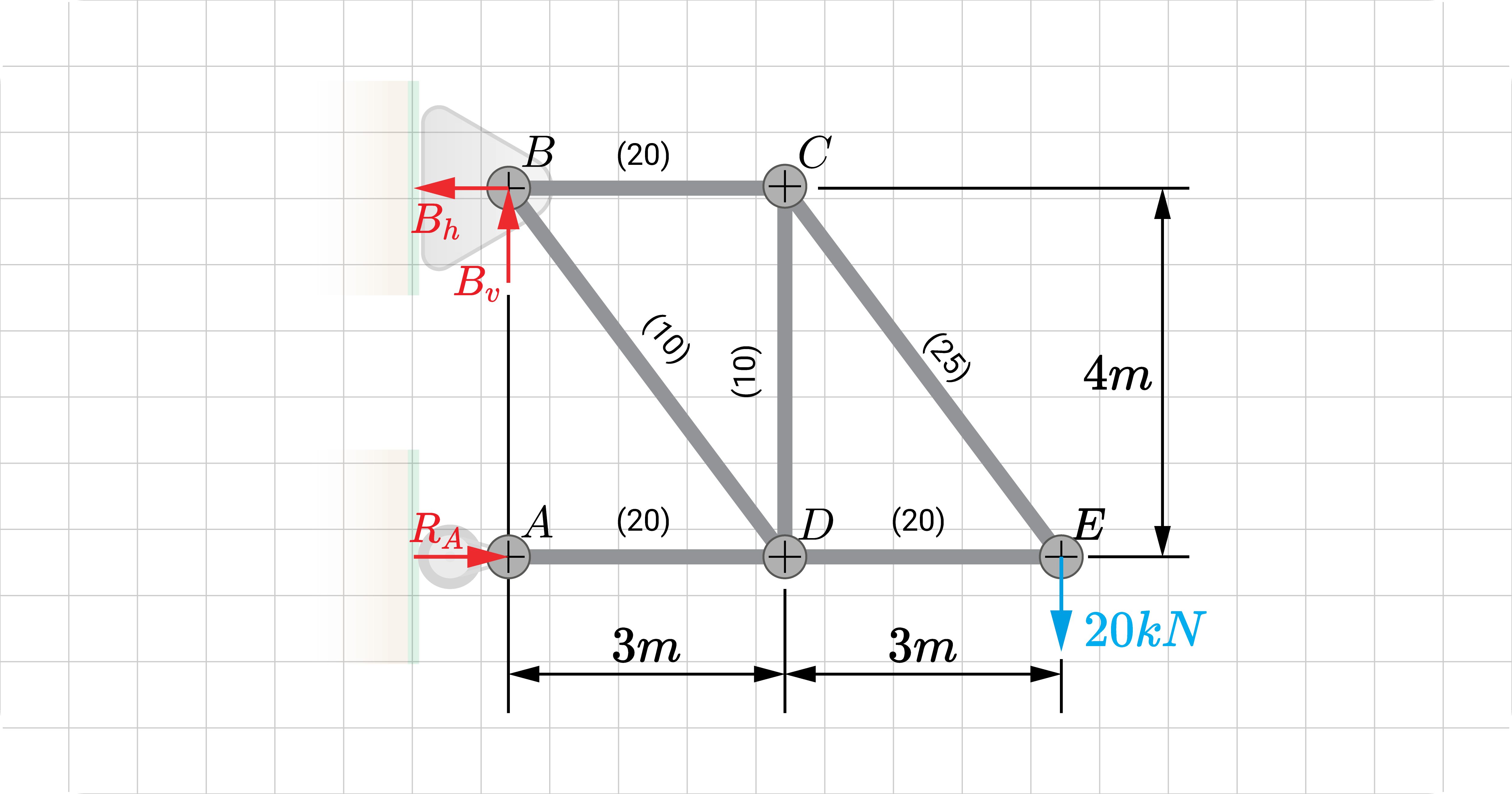
To start, we shall consider a simple truss. It has a \(20 kN\) point load at \(E\). The value inside the parenthesis () is the member's cross-sectional area \(A\) in square centimeters.
Say that we are interested in finding the resultant translation \(\Delta_E\) of point E, as well as the rotation of member \(CE\) \(\theta_{CE}\). The resultant deflection \(\Delta_E\) implies to us that we need to find the horizontal and vertical translation \(\Delta_{E_h}\) and \(\Delta_{E_v}\) of \(E\)
For this problem, we'll assume that all members are made of the same material so that the modulus of elasticity \(E\) is constant.
Main Solution
Want to access the remaining content?
You're a Member!
Click to expand on exclusive content
Want to access the remaining content?
Become a Member
When you sign-up and subscribe to WeTheStudy, you’ll get the following benefits:
The first step is to represent each deflection component with a unit load and apply it to a corresponding virtual structure. We would also need to assume the direction of each element:
Horizontal translation at \(E\) is to the right; hence, the applied unit load also acts to the right.
Vertical translation at \(E\) is downward; hence, the applied unit vertical load also acts downward.
To find the rotation of member \(CE\), we represent it with two equal parallel forces applied perpendicularly at both ends of member \(CE\); so that the effect resembles a unit couple. We'll assume this couple acts clockwise to represent a clockwise rotation.
Formulate S, u, A, and E Equations.
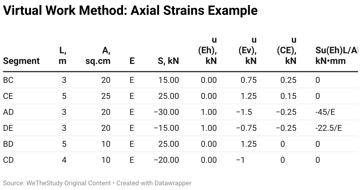
After creating the virtual structures, it's time to find \(S\), \(u\), \(L\), \(A\), and \(E\) of each member for both the virtual and superimposed structures. As seen below, creating a matrix that summarizes all these variables is best for this approach.
We first identify \(L\), \(A\), and \(E\) for each truss member. If these variables vary along the member's length, we must express it in terms of \(x\) (member's local axis). Since our example deals with constant axial rigidity \(AE\), we do not have to worry about those instances.
Next, we solve for the bar forces \(S\) of the superimposed structure, as well as the bar forces of the virtual equivalent \(u_h\), \(u_v\), and \(u_{\alpha_{CE}}\). We can do this exactly using the method of joints, the method of sections, or a combination of both, depending on the truss type.
We summarise our results for all bar forces \(S\), \(u_h\), \(u_v\), and \(u_{\alpha_{CE}}\) in the table. Positive bar forces are in tension, while negative-sensed bar forces are in compression.
The negative sign of the horizontal translation means that the movement of joint \(E\) is to the left instead of the right. On the other hand, the positive sign of vertical translation means that the movement is indeed downward. With these two translation components, we can finally solve for the resultant deflection: