
When a structure experiences flexural loads, it will experience shear \(V\) and moment \(M\).
What are Shear and Moment?
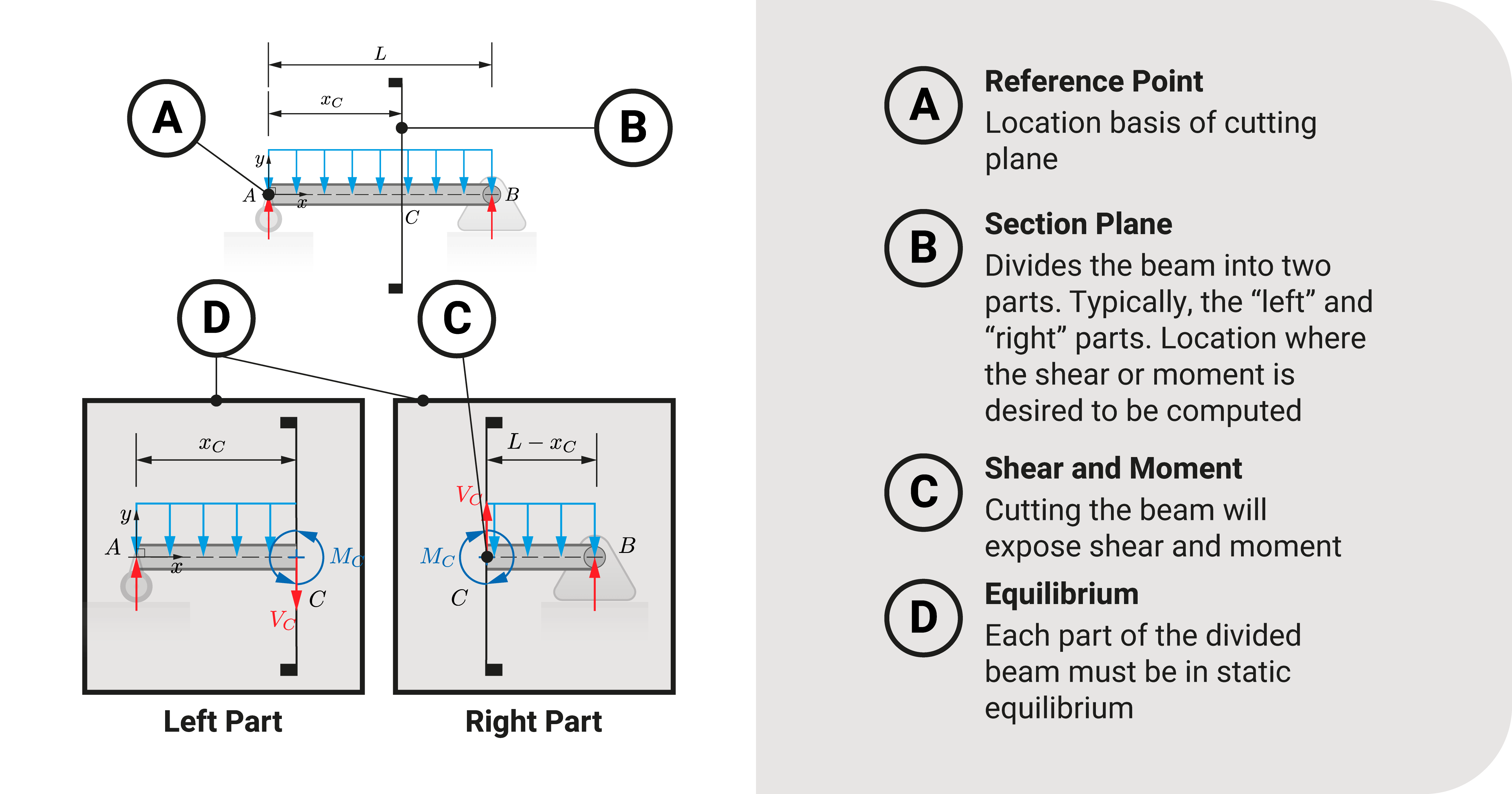
Let's consider a simple beam with a uniform distributed load throughout its length and cut it at any point between its ends. We'll have two parts: a left and a right section.
Naturally, this structure must be in a state of equilibrium. That includes when we cut it into two parts.
Let's consider the left section. The external loads acting on it are the reaction and the load. For this part to be in equilibrium, the beam's fibers must provide a resisting force and moment to counteract these external forces.
The force resistance of the beam is what we call shear \(V\), while the moment resistance is its bending moment \(M\).
These two quantities will vary throughout their length. For example, the shear and moment at one end of the beam are different than at the midpoint. These quantities will depend on what point along the structure we wish to investigate.
Shear and Moment Conventions
When we compute for shear and moment using equilibrium, these two quantities may be positive or negative. So, what does positive or negative shear or moment mean?
The sign will refer to the way the beam will bend. There are two conventions: (1) concaved upward convention and (2) concaved downward convention.
Concaved Upward Convention
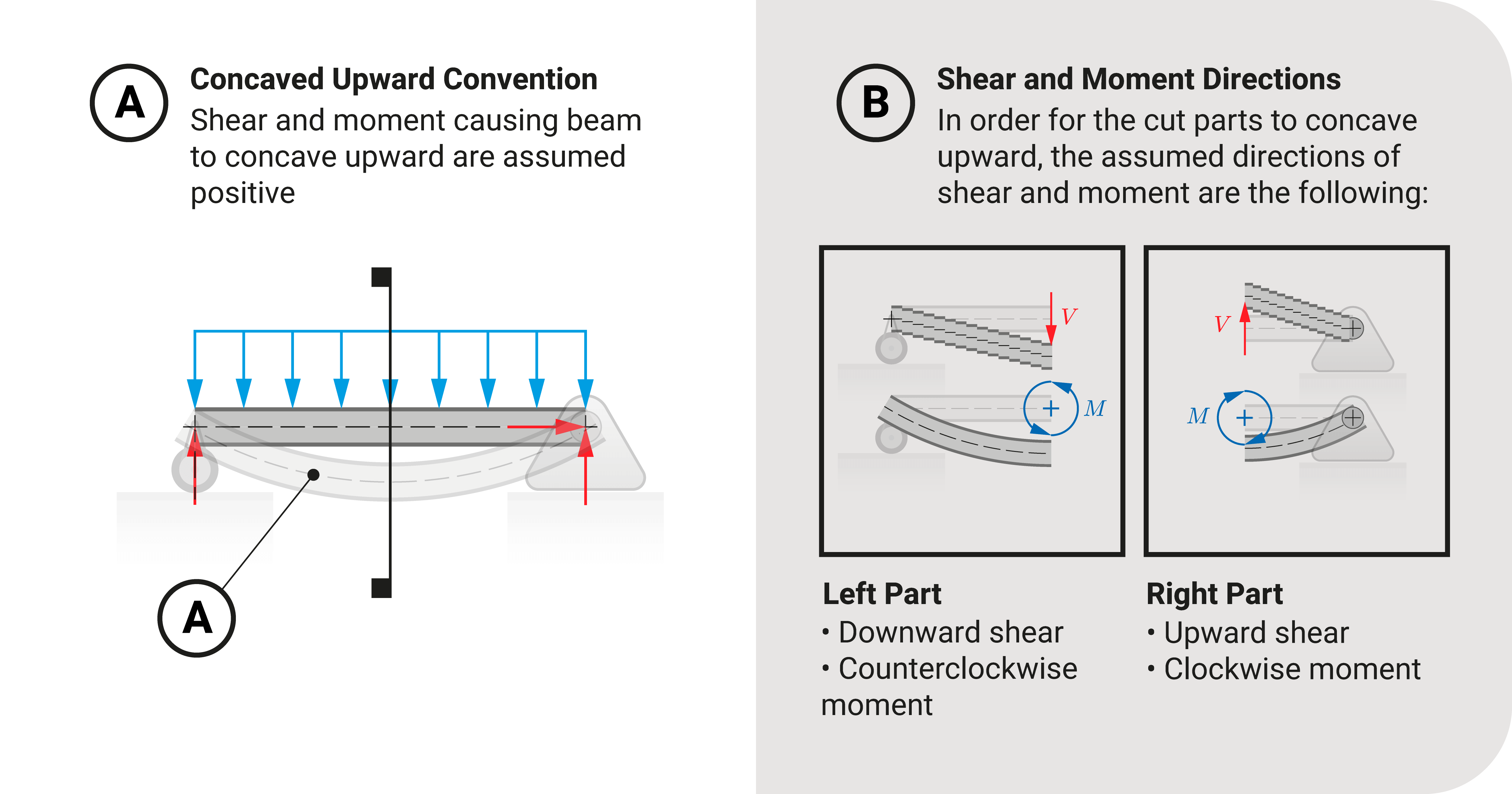
Most classical approach references will use this convention:
- A positive shear or moment means the member concaved upward.
- A negative shear or moment means the member concaved downward.
If we investigate the left section, the exposed shear acts downward (causes plane fibers of the beam to slide downward), and the moment is counterclockwise. These directions would concave the left part upward.
Concaved Downward Convention
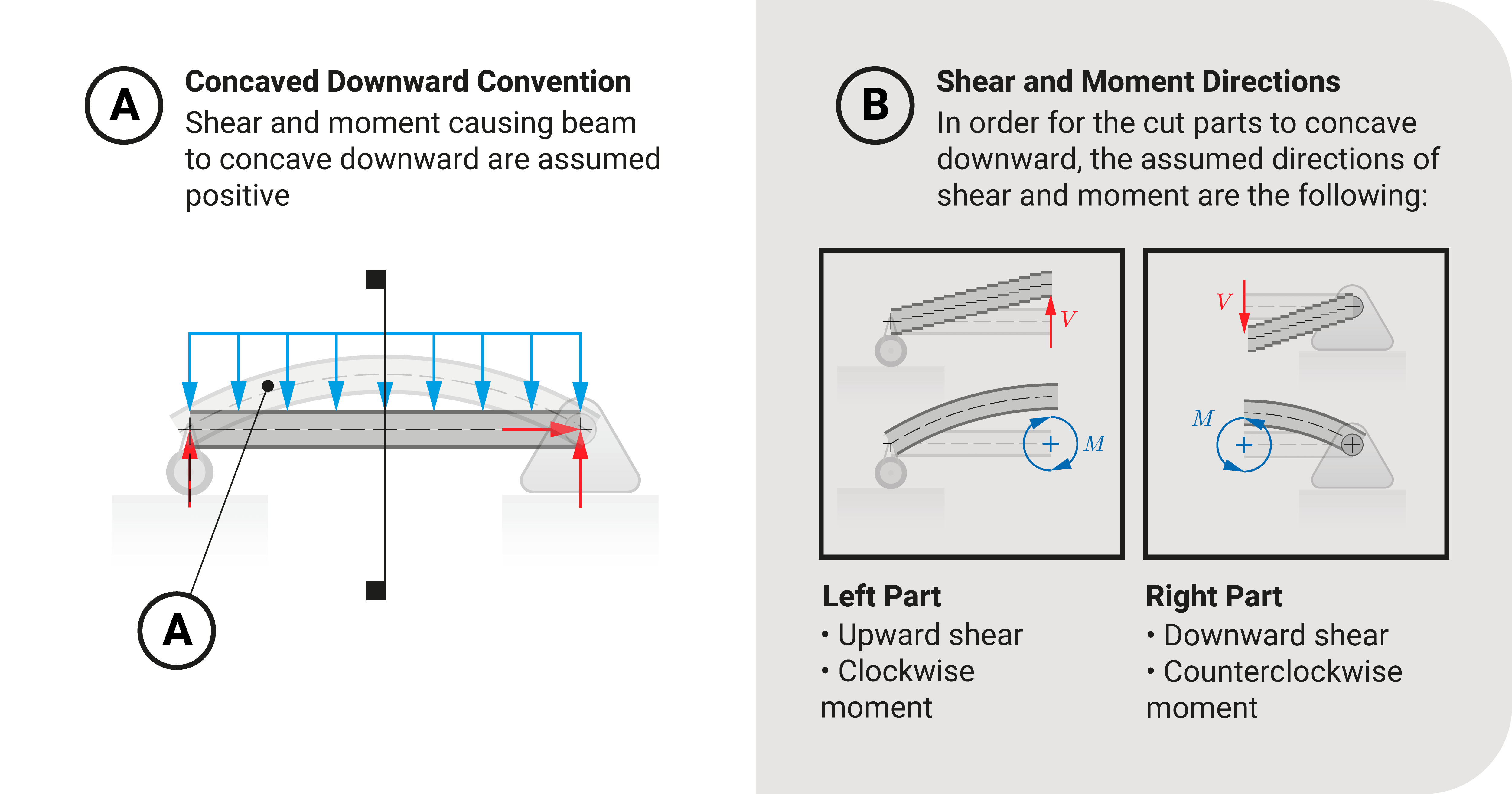
The concaved downward convention is the opposite of the previous convention:
- A positive shear or moment means the member concaved downward.
- A negative shear or moment means the member concaved upward.
If we investigate the left section, the exposed shear acts upward (causes plane fibers of the beam to slide
upward), and the moment is clockwise. These directions would concave the left part downward.
Modelling Shear and Moment
In this section, we shall explore how to model shear and moment. We will use the concaved upward convention for the rest of this reference.
Analytical: Shear and Moment Equations
We can model shear and moment from an analytical perspective. The standard way to describe it is to express \(V\) and \(M\) as a function of \(x\). The variable \(x\) stands for the position of the cutting plane from a reference.
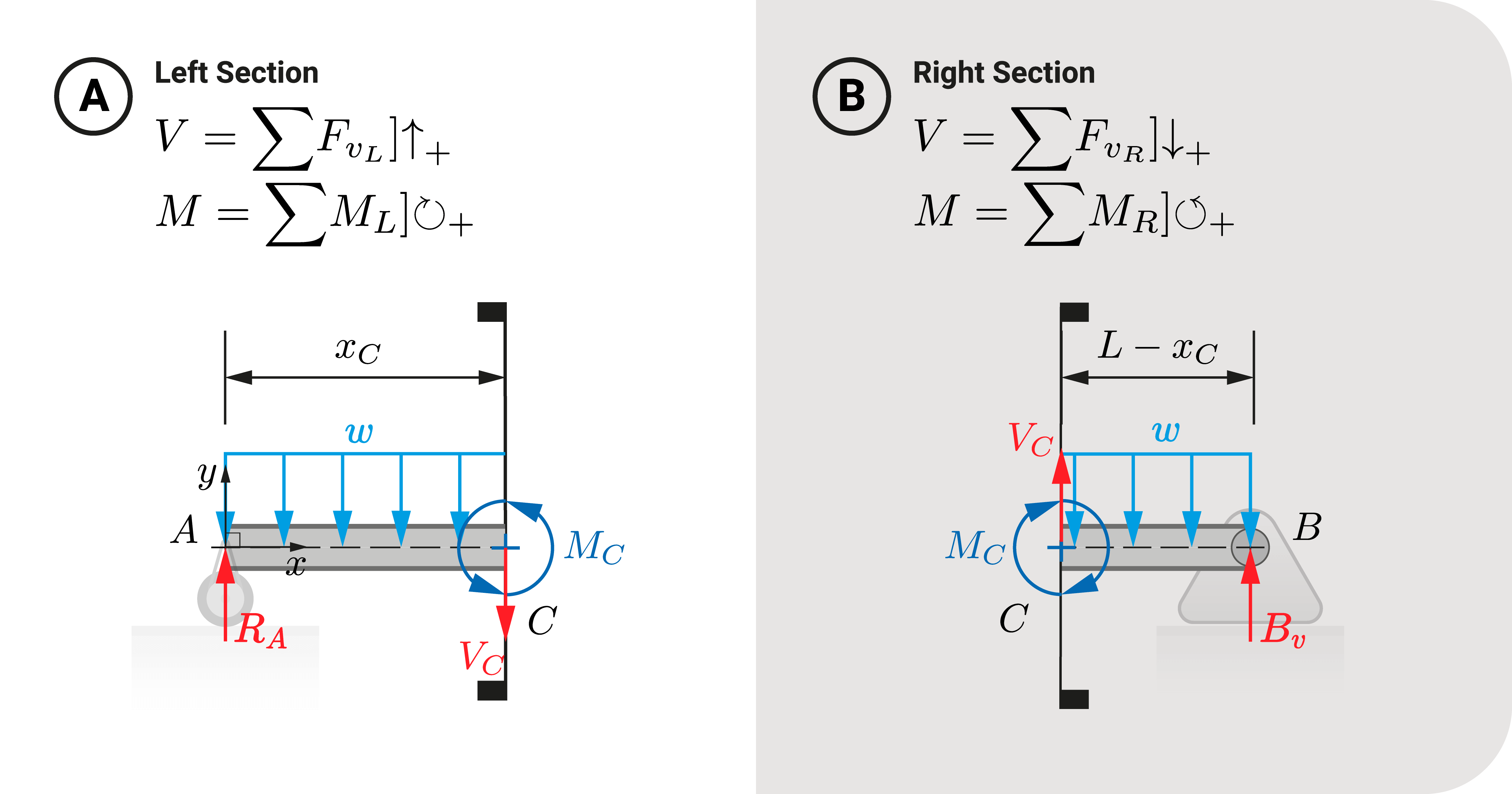
To create these functions, we use the equilibrium equations. Starting with the left section:
- \(V=(\sum{F_v})_L]\uparrow_+\). All external forces acting upward are positive, while downward are negative.
- \(M=(\sum{M})_L]\circlearrowright_+\). All external moments acting clockwise are positive, while counterclockwise are negative.
On the other hand, if we investigate the right section, the exposed shear acts upward, and the moment is clockwise. Likewise, these directions would concave the right part upward. As a result, the equations become:
- \(V=(\sum{F_v})_R]\downarrow_+\). All external forces acting downward are positive, while upward are negative.
- \(M=(\sum{M})_R]\circlearrowleft_+\). All external moments acting counterclockwise are positive, while clockwise are negative.
After applying equilibrium, we get the shear and moment equations. Using these expressions, we can compute the \(V\) and \(M\) at any position \(x\) we want to investigate.
It is important to note that structures may change in loading condition or cross-sectional properties along their length; hence, we must explicitly define the domain of shear and moment functions. These equations apply only to a specific range of \(x\). We can discover more of this using an illustrative problem later on.
Graphical: Shear and Moment Diagrams
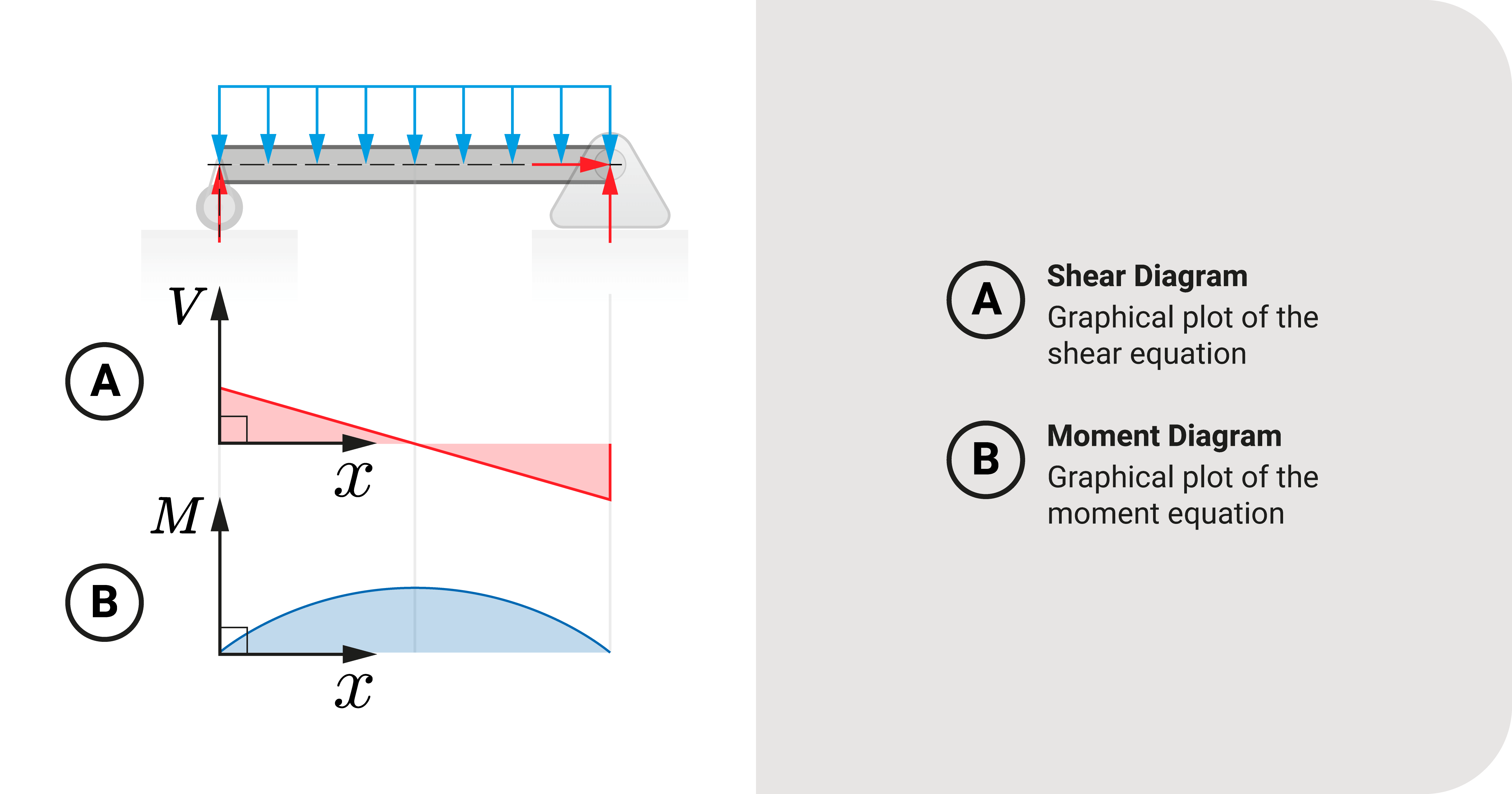
Since shear and moment equations are mathematical functions, we can plot these into a graph and visualize these equations. These graphs \(V-x\) or \(M-x\) are the shear and moment diagrams.
These graphs are standard tools to visualize how shear and moment act along the structure under the effect of external loads.
A fascinating relationship exists between a structure's external load, shear, and moment. We can discover more about it in this link.
Applications
Below are examples that demonstrate how to model shear and moment as well as evaluate it:
- Example of constructing shear and moment equations and diagrams
- How to assess shear and moment at a point
Summary
Let's summarize:
When a structure experiences flexural loads, it will experience shear \(V\) and moment \(M\).
When we cut a flexural member at a point, we divide it into two parts. For each component to be in equilibrium, the beam's fibers must provide a resisting force and moment to counteract these external forces. The resisting force and moment are shear \(V\) and moment \(M\), respectively.
There are two conventions of shear and moment: the concaved upward and concaved downward.
Most references follow the concaved upward convention: a positive shear or moment means the member concaved upward, while a negative sense tells us the member concaved downward.
We can model shear and moment analytically or graphically.
The standard way to describe shear and moment analytically is to express these as a function of position \(x\). Such equations are what we call shear and moment equations.
If we investigate the left section, the exposed shear acts downward, and the moment is counterclockwise. These will concave the beam upward. In addition, the equilibrium equations become (1) \(V=(\sum{F_v})_L]\uparrow_+\), and (2) \(M=(\sum{M})_L]\circlearrowright_+\).
If we investigate the right section, the exposed shear acts upward, and the moment is clockwise. These will concave the beam upward. In addition, the equilibrium equations become (1) \(V=(\sum{F_v})_R]\downarrow_+\), and (2) \(M=(\sum{M})_R]\circlearrowleft_+\).
Since shear and moment equations are mathematical functions, we can plot these into a graph and visualize these equations. These graphs \(V-x\) or \(M-x\) are the shear and moment diagrams.


