Around the 1750s, Bernoulli and Euler created theories on how beams behave under the influence of loads – specifically, how they deflect and act under bending. Their model is what we use to describe the behavior of beams under flexural stresses.

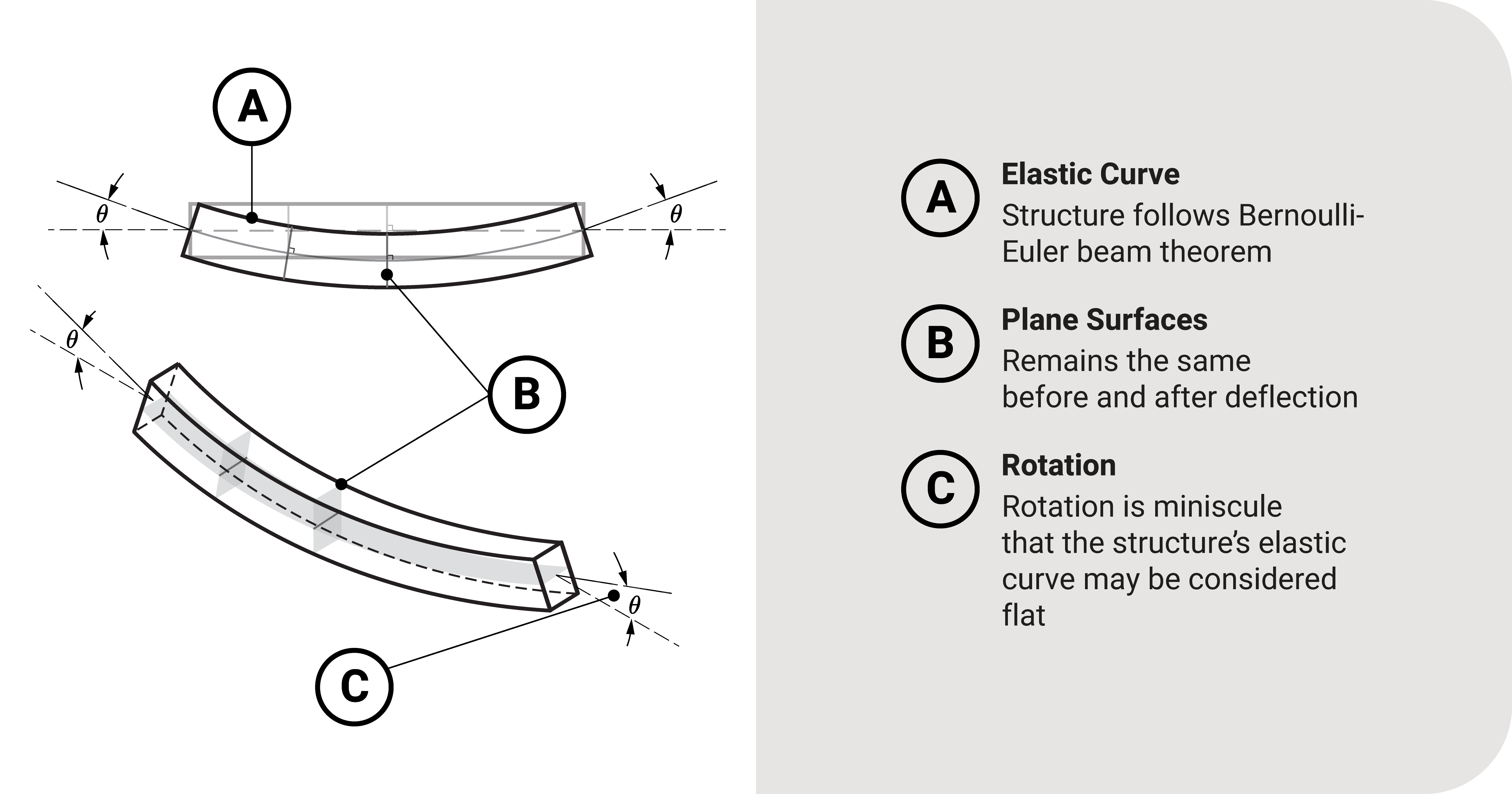
From their works, there were two major assumptions:
- When a beam deflects, plane sections remain the same.
- The rotation \(\theta\) of a point on the beam is so tiny that its elastic curve may be considered flat.
Bernoulli-Euler Beam Equation
Derivation
From these assumptions, we can formally derive an expression for solving the translation and rotation of beams at any point from a selected origin (usually the left end).
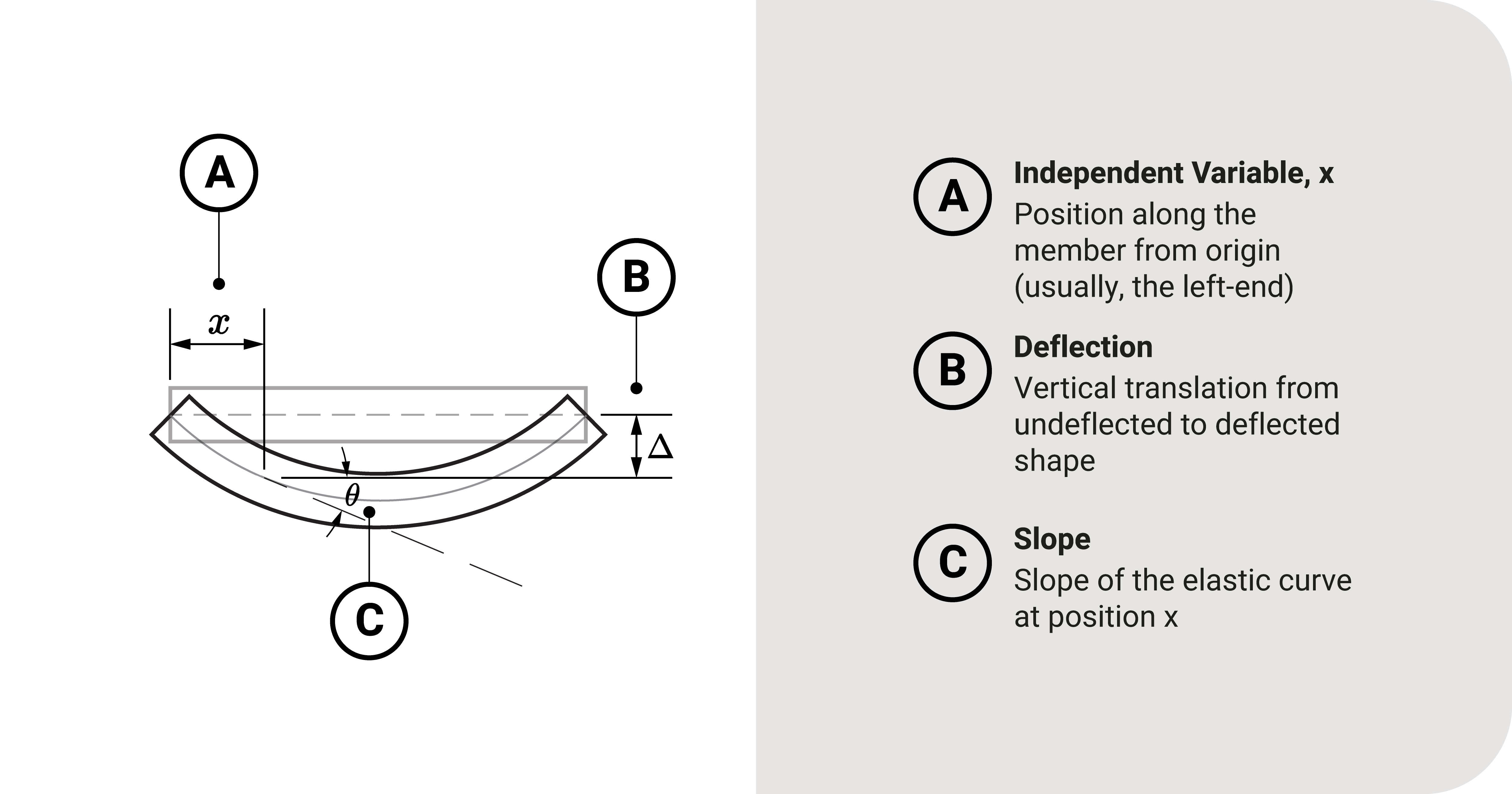
Say we have a deflected beam as shown due to bending:

Let \(x\) be the location at which we would want to find the deflection of the beam from the origin and \(\Delta\) be the vertical translation of a point at \(x\). The former is the independent variable, while the latter is the dependent variable. Our goal here is to relate these two variables through a function.
We can exactly do that by taking the slope of the elastic curve at \(x\). Since the slope is equal to the first derivative, \(\Delta\) and \(x\) can be expressed as:
\(\tan\theta=\frac{d\Delta}{dx}\)
Because we have assumed that the slope (or rotation \(\theta\)) is so tiny, the tangent of the angle \(\theta\) is almost equal to the angle itself.
\(\tan\theta\approx \theta=\frac{d\Delta}{dx}\)
Let's take the derivative of this expression with respect to \(x\) to obtain the following:
Equation 1: \(\frac{d\theta}{dx}=\frac{d^2\Delta}{dx^2}\)
This equation describes the relationship between \(\Delta\) and \(x\) through \(\frac{d\theta}{dx}\).
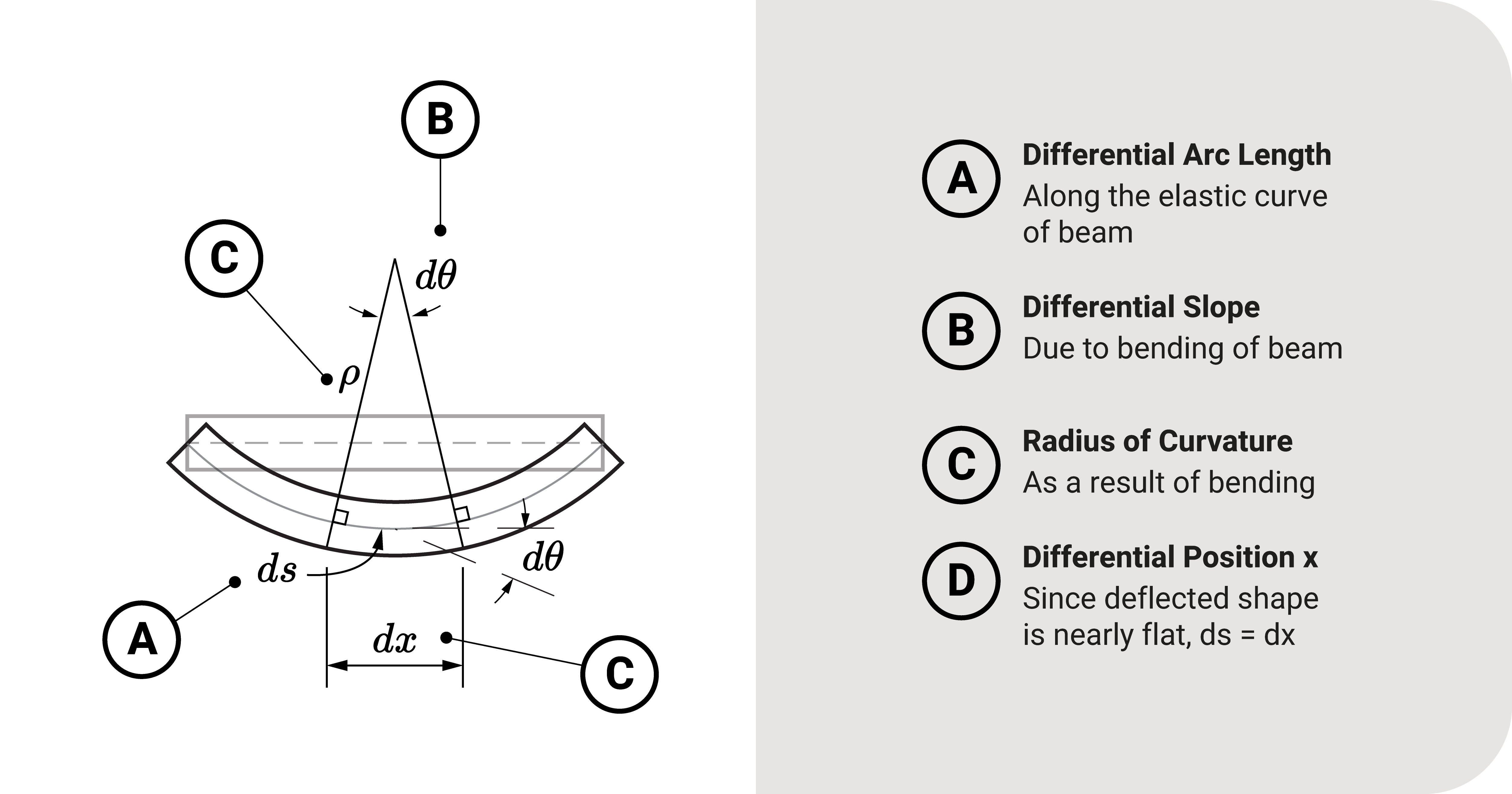
Next, we need to expound on \(\frac{d\theta}{dx}\). Let's consider the illustration below.

We take a differential arc \(ds\) of the beam's deflected shape with a radius of curvature \(\rho\) made by a central angle \(d\theta\). This consideration is possible because we have assumed that the plane sections of the beam remain the same after deflection. Also, because the deflected shape is almost flat, \(ds=dx\). Using the arc length formula and isolating \(\rho\) on one side:
Equation 2: \(\frac{1}{\rho}=\frac{d\theta}{dx}\)
The term \(\frac{1}{\rho}\) in Equation 2 is known as the beam's curvature. Any Strength of Materials reference will tell you that this expression is related to the internal moment \(M\) at position \(x\):
Equation 3: \(\frac{1}{\rho}=\frac{M}{EI}\)
Equation
With Equations 1, 2, and 3, we can relate these expressions to obtain:
Bernoulli-Euler Beam Equation: \(\frac{d^2\Delta}{dx^2}=\frac{M}{EI}\)
This second-order differential equation is known as the Bernoulli-Euler Beam Equation and is our primary tool to solve for beam deflections.
- \(x\) is the point at which we'd like to find the deflection component.
- \(\Delta\) is the translation of the beam at position \(x\).
- \(M\) is the bending moment expression in terms of \(x\).
- \(E\) is Young's Modulus - a property of the beam.
- \(I\) is the moment of inertia of the beam's cross-section at \(x\).
The product \(EI\) is also known as flexural rigidity - a property that tells how resistant an object is to deflection or deformation in bending.
When the deflected shape obey the Bernoulli-Euler Beam Equation, we also call the shape as the elastic curve (since the deflected shape obeys the elastic region).
Summary
Let's summarize:
Around the 1750s, Bernoulli and Euler created theories on how beams behave under the influence of loads.
From their works, there were two major assumptions: (1) when a beam deflects, plane sections remain the same, and (2) the rotation \(\theta\) of a point on the beam is so tiny that its elastic curve may be considered flat.
The second-order differential equation, known as the Bernoulli-Euler Beam Equation \(\frac{d^2\Delta}{dx^2}=\frac{M}{EI}\), is our primary expression to solve for beam deflections.


