This post shows a sample linear structural analysis of a 2D determinate compound beam with static loads using the classical approach.
This example shows units in SI and English. The English system is in parentheses.
In terms of computations, however, it will primarily be in the SI system. The author converted the answer from the SI solution to English to reflect the latter system. It only applies to definite values, not equations.
We will update this post to reflect solutions in the English system soon.
Structural Model
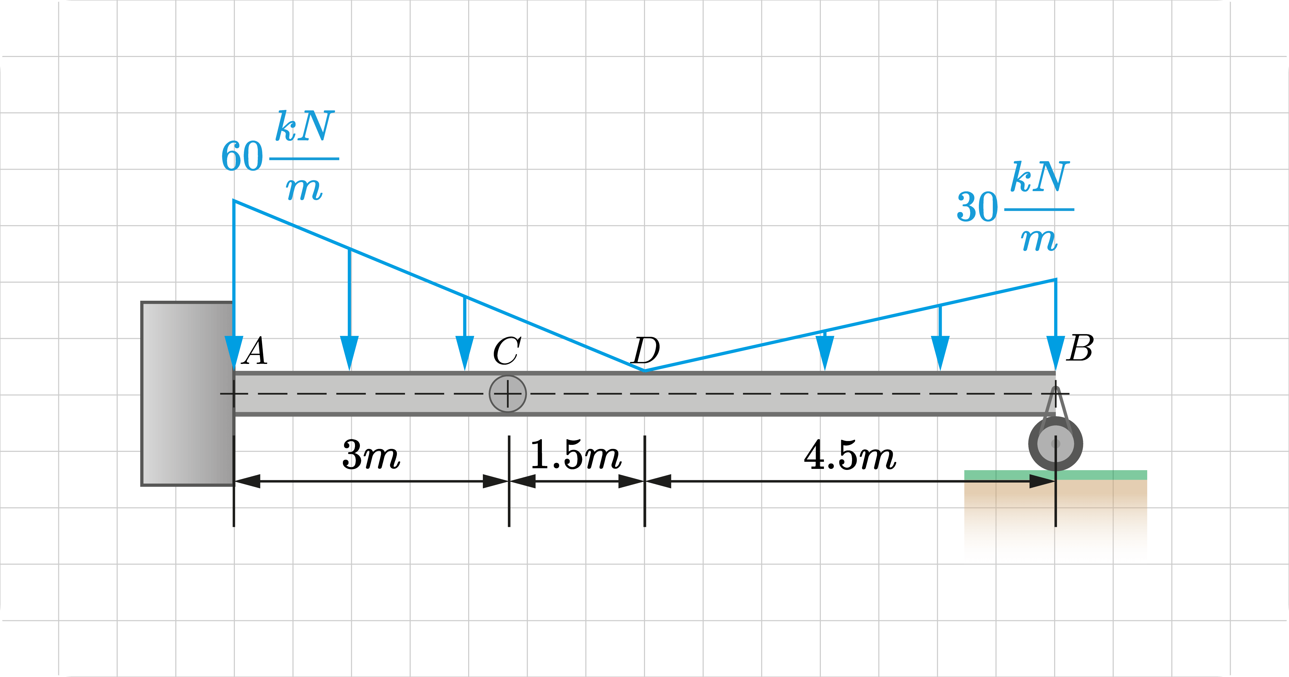
Let's consider a compound beam example. In this instance, we have two beams connected by an internal hinge. It is assumed to have a uniform section of the same material.
Structural Loads
The beam has the following static loads:
- A varying linear load from \(60kN/m (4.11kip/ft)\) to \(0\) ↓.
- A varying linear load from \(0\) to \(30kN/m (2.06kip/ft)\) ↓.
We can see the position and direction of these loads in the following figure. We can talk more about this in preparation.
Structural Analysis
Type of Analysis: Classical Approach, Linear Analysis, Static Loads, Plane Beam, Determinate Beam
Preparation
Before analyzing a structure, we'll need to make some preparations first. That includes setting up our references and finding their determinacy.
Set-Up References
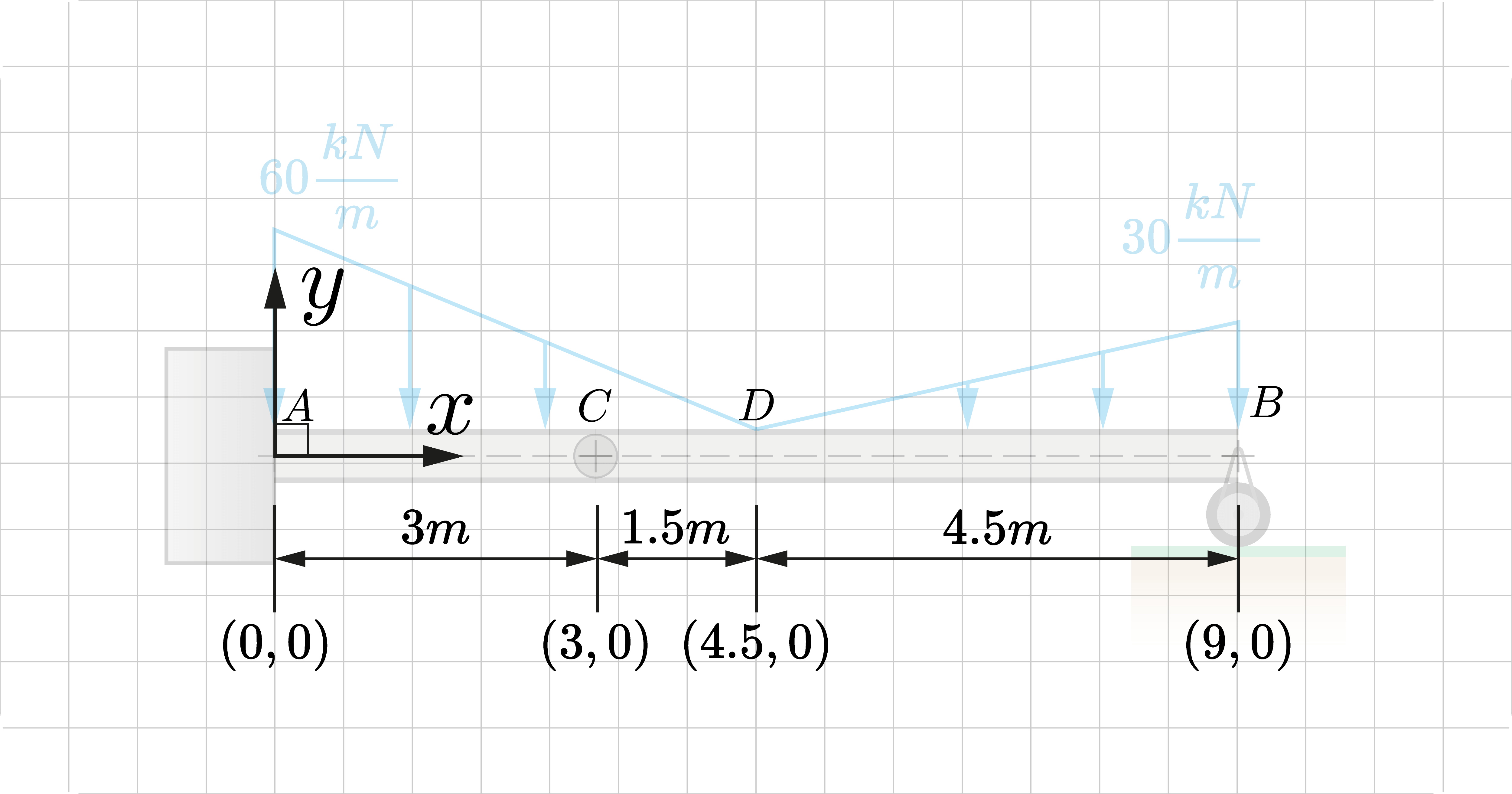
An excellent structural analysis must have a uniform mathematical understanding of the structure. It ensures that other people can easily understand your results.
We first place a Cartesian grid with its origin defined by our preference. In this case, let's assign the origin \(A(0, 0)\) at the leftmost point of the beam. Consequently, the x-axis will run along the length of the beam with the y-axis perpendicular to it at the origin.
We also need to identify the location of all points of interest: the location of supports, change in loads, and differences in the beam's cross-sectional properties. Starting from \(A\) and going toward the other end, we identify the following points of interest:
- \(A(0.0m, 0.0m), A(0.0ft, 0.0ft)\). The fixed support and the start of the varying linear load of \(60kN/m (4.11kip/ft)\).
- \(C(3.0m, 0.0m), C(9.84ft, 0.0ft)\). The location of the internal hinge.
- \(D(4.5m, 0.0m), D(14.76ft, 0.0ft)\). The end of the varying linear load \(0\) and the start of the other varying linear load \(0)\), and
- \(B(9.0m, 0.0m), B(29.53ft, 0.0ft)\). The end of the varying linear load of \(30kN/m (2.06kip/ft)\) and the roller support
You can label each joint according to your preference. The most important thing is that its coordinates must be defined appropriately.
Determinacy
We need to find the structure's determinacy \(D\) to know our approach.
For a 2D beam, it is:
\(D=r-(3+e_c)\)
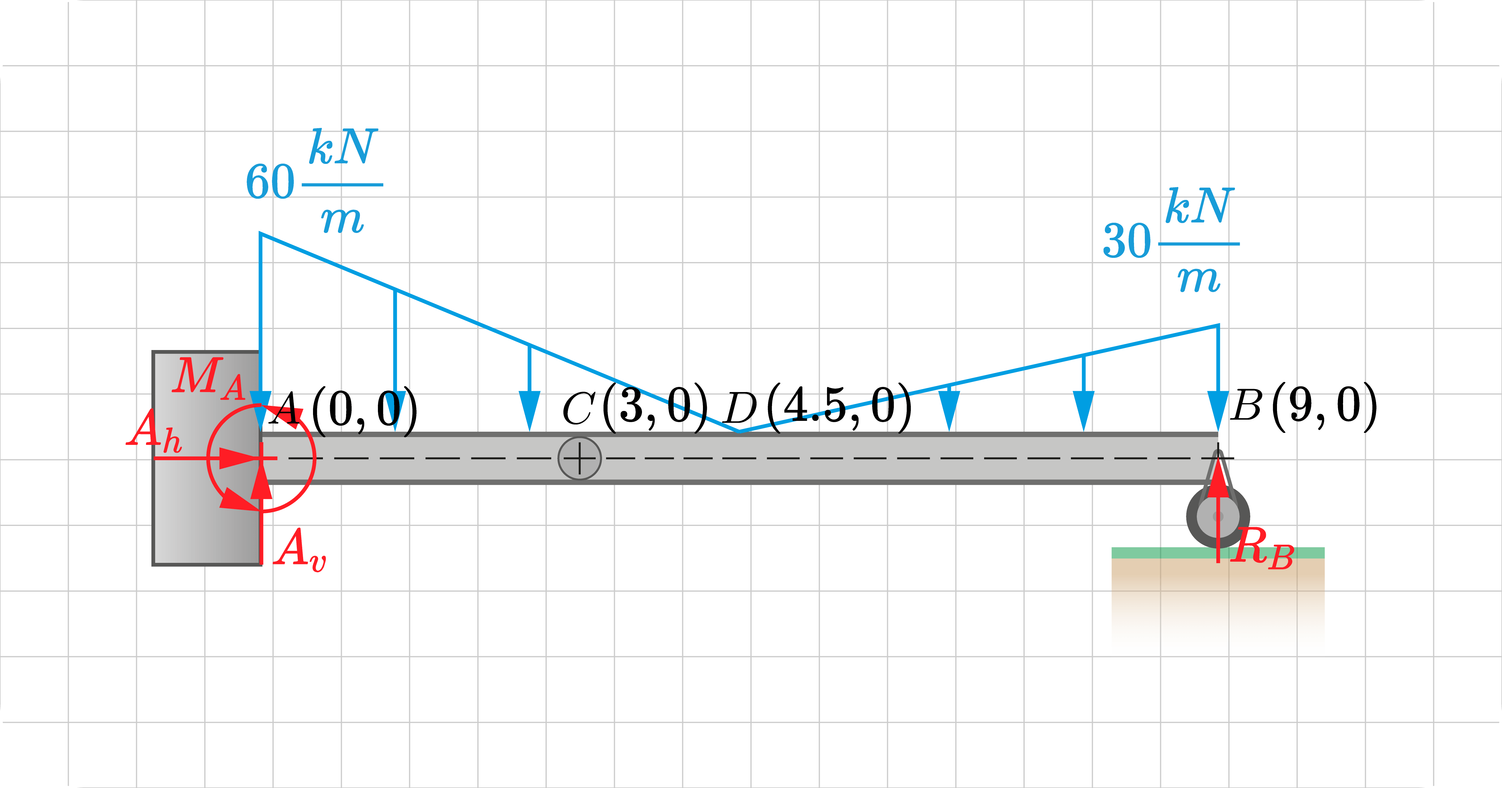
This beam example have four reaction components: \(A_h\), \(A_v\), \(M_A\), and \(R_B\), and one internal connection at joint \(C\) \(e_c = 1\); hence \(D=0\)
\(D=4-(3+1)=0\)
The internal connection hinge at \(C\) provides an additional condition to help us analyze the structure. At the said point, the moment experienced is zero.
A determinacy of zero indicates that the structure can be analyzed using only the equilibrium equations.
Main Analysis
Stability
The first requirement is to know if our structure is externally and internally stable.
Let's examine its external stability first:
- The reaction components \(A_h, A_v, M_A, R_B\) are not collinear, parallel, or concurrent with each other.
- The determinacy is equal to zero.
From these observations, we can conclude the beam is externally stable. In terms of its internal stability, the beam arrangement doesn't pose any risks of excessive deformation or immediate collapse; hence, it's internally stable.
Since the structure is externally and internally stable, we can proceed with the analysis. If it is unstable, we may have to adjust its model before proceeding.
Reactions
The second requirement for a complete analysis is to compute the support loads of the structure. Solving for the components enables us to understand the transfer of loads.
For a determinate structure, solving for its reactions is straightforward. To solve it, always remember that the whole model must obey the laws of equilibrium.
As a demonstration, we first break the support loads into their components (not their resultant) along the axes. In our example, we have four components:
- We assume \(A_h\) to be acting towards the right, and
- \(A_v\) and \(R_B\) are acting upwards.
- \(M_A\) is a counterclockwise moment.
Break Down the Beam
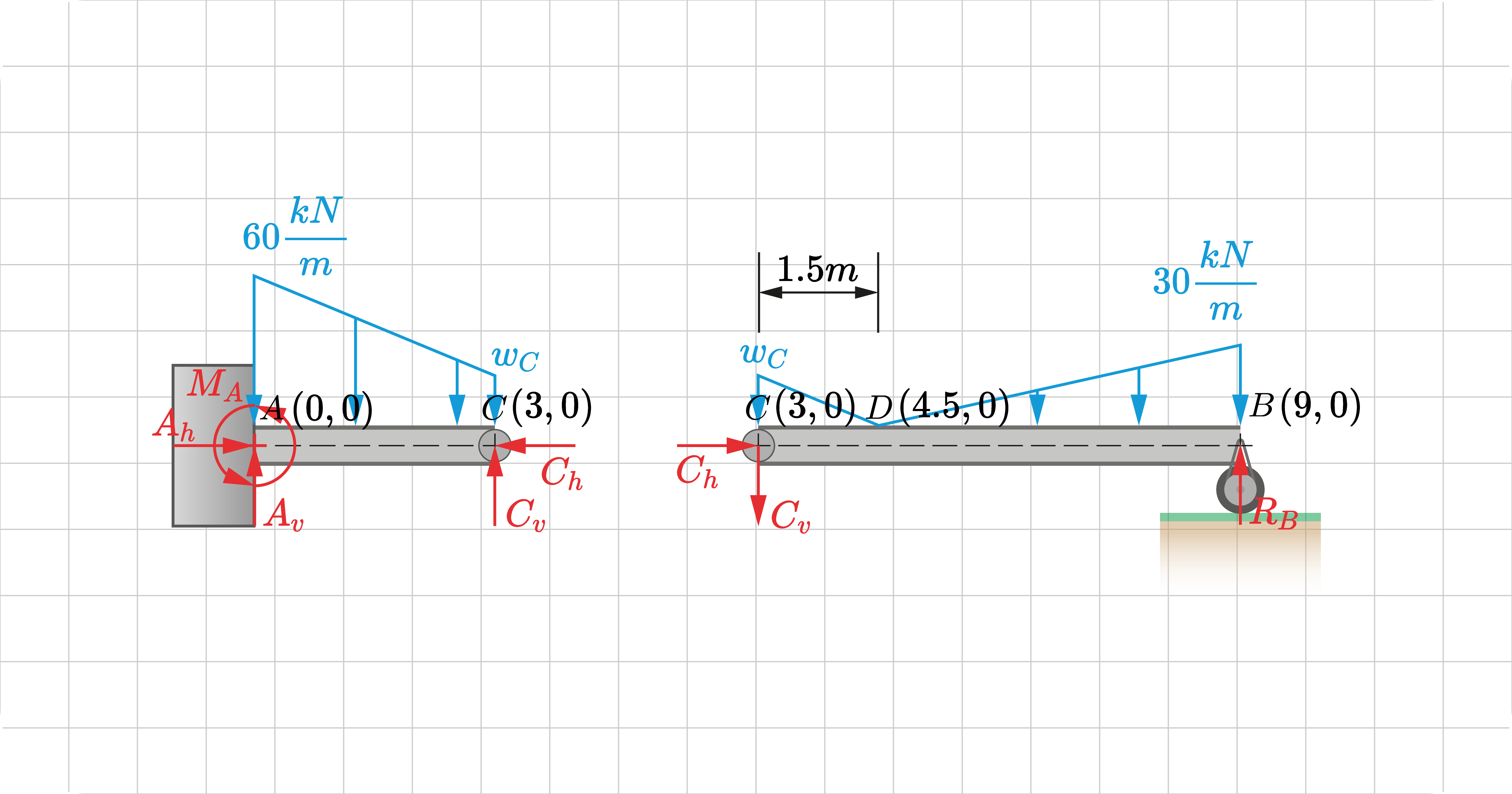
As a preliminary step in solving the reactions of compound beams, we "disconnect" it at points of internal connections. In our example, it would be the hinge at point \(C\).
As a result, we will have the free-body diagrams (FBD) of each element of the compound beam - FBD CB and FBD AC.
For each diagram, we have the joint \(C\). At this point, the hinge will provide two forces: \(C_h\) and \(C_v\), which are unknown.
At this hinge, it will provide an additional condition: the summation of moments at that point is zero. We can use this to help us solve the reactions.
In terms of its directions, \(C_h\) and \(C_v\) are also unknown. Normally, one assumes the direction. Said directions must be opposite for each FBD to comply with Newton's Third Law.
- In FBD CB, \(C_h\) acts to the right while \(C_v\) acts downward.
- In FBD AC, \(C_h\) acts to the left while \(C_v\) acts upward.
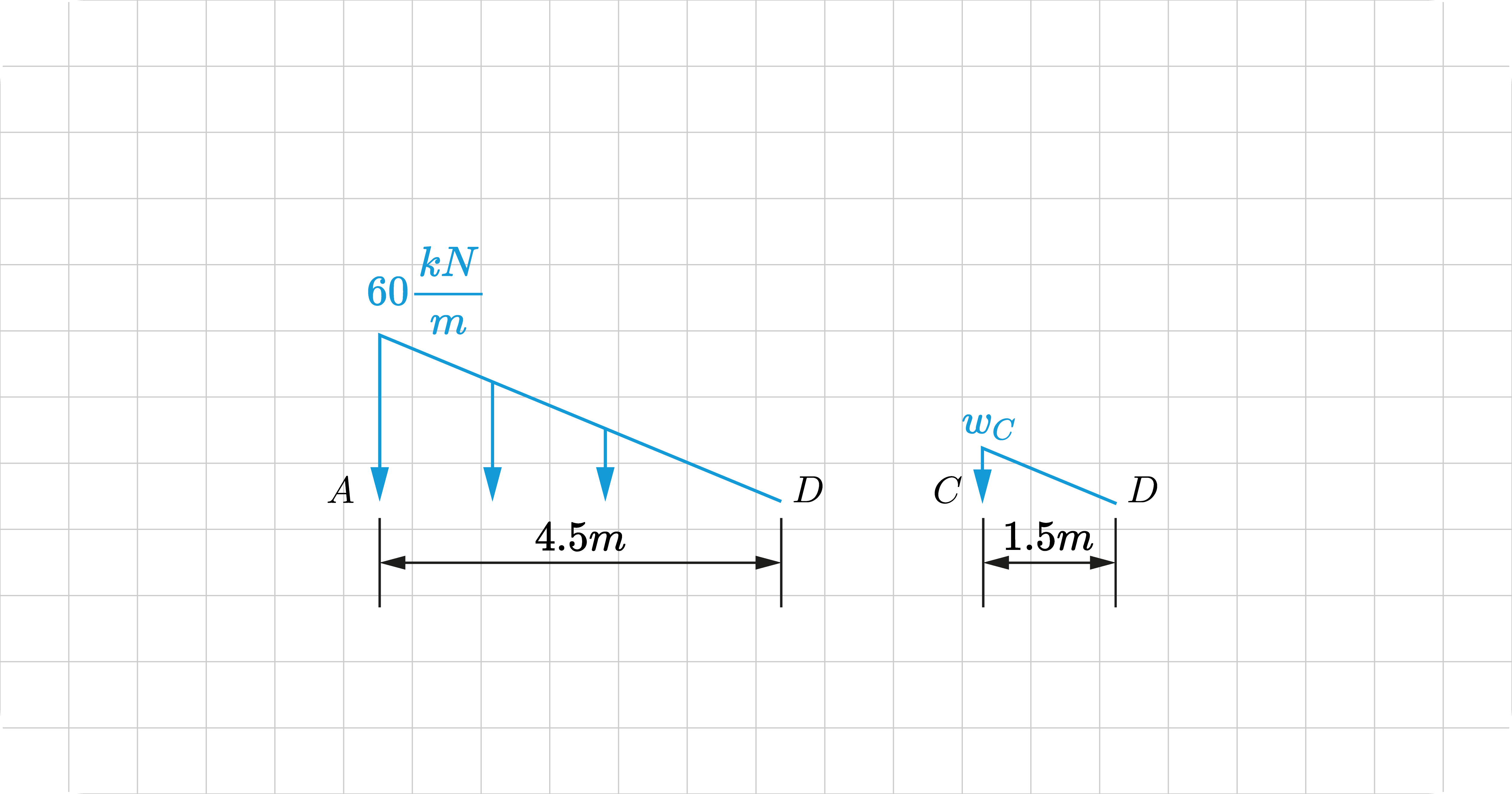
Before moving on, it would be wise to compute the load at point \(C\) for FBD CB. We can do this by ratio and proportion since it is a varying linear load:
\(\frac{60}{4.5}=\frac{w_C}{1.5}\)
\(w_C=20kN/m (1.37kip)\)
To solve for the reactions, as well as the hinge, all we have to do is to apply the equilibrium principle to these individual FBDs. Let's demonstrate below:
Free Body Diagram CB

Applying the equilibrium equations:
\(\sum{F_h}=0]\space{\rightarrow_+}\)
\(C_h=0\)
\(\sum{M_C}=0]\space{\circlearrowright_+}\)
\(\frac{1}{2}(1.5)(20)(\frac{1}{3}\times1.5)+\frac{1}{2}(4.5)(30)(1.5+\frac{2}{3}\times4.5)-R_B(1.5+4.5)=0\)
\(R_B=51.875kN (11.66kip)\)
\(\sum{F_v}=0]\space{\uparrow_+}\)
\(51.875-\frac{1}{2}(4.5)(30)-\frac{1}{2}(1.5)(20)-C_v=0\)
\(C_v=-30.625kN (-2.10kip)\)
From our calculations, the reaction components and the hinge forces are:
\(C_h=0\)
\(R_B=51.875kN (11.66kip)\)
\(C_v=-30.625kN (-2.10kip)\)
If our answer is negative, the assumed direction is wrong, and the correct one is the opposite.
- \(C_v\) should not be downward but rather upward in FBD CB. Consequently, in FBD AC, \(C_v\) must act below.
Free Body Diagram AC

Applying the equilibrium equations:
\(\sum{F_h}=0]\space{\rightarrow_+}\)
\(A_h-C_h=0\)
\(A_h=0\)
\(\sum{F_v}=0]\space{\uparrow_+}\)
\(A_v-30.625-\frac{1}{2}(3)(40)-3(20)=0\)
\(A_v=150.625kN (33.86kip)\)
\(\sum{M_A}=0]\space{\circlearrowright_+}\)
\(-M_A+\frac{1}{2}(3)(40)(\frac{1}{3}\times3)+3(20)(\frac{1}{2}\times3)+30.625(3)=0\)
\(M_A=241.875kN•m (178.40kip•ft)\)
From our calculations, the reaction components and the hinge forces are:
\(A_h=0\)
\(A_v=150.625kN (33.86kip)\)
\(M_A=241.875kN•m (178.40kip•ft)\)
If our answer is negative, the assumed direction is wrong, and the correct one is the opposite.
At this point, we have now solved the reaction components.
\(A_h=0\)
\(A_v=150.625kN (33.86kip)\)
\(M_A=241.875kN•m (178.40kip•ft)\)
\(R_B=51.875kN (11.66kip)\)
We can verify the results by applying the equilibrium principle to the whole structure.
Force Analysis
The third requirement for a complete analysis is understanding the internal force and stress developed on the structure due to the applied loads.
We have four types of stresses to analyze: axial, shear, moment, and torsion. Typically, we do these by modeling the behavior using functions and diagrams.
In our example, we limit to shear and moment only.
Modeling Shear and Moment Behavior
We can use shear and moment equations and graphs to describe the beam's internal behavior.
Creating these equations and diagrams deserves a separate section. Learn more about how to construct these using these individual posts:
The following shows our beam's shear and moment equations and diagrams. You can view the complete solution soon.
Shear
SI Equations
\(V_{AD}=\frac{40}{6}x^{2}-60x+140.5,\left\{0\le x\le4.5\right\}\)
\(V_{DB}=-\frac{10}{3}x^{2}+30x-62,\left\{4.5\le x\le9\right\}\)
Diagram
Moment
SI Equations
\(M_{AD}=\frac{40}{18}x^{3}-30x^{2}+140.5x-150.75,\left\{0\le x\le4.5\right\}\)
\(M_{DB}=-\frac{10}{9}x^{3}+15x^{2}-62x+153,\left\{4.5\le x\le9\right\}\)
Diagram
In the shear diagram, you'll see that we have a point of zero shear at \(x= 5.785\). At this point, it is a relative maximum. If you look at the moment diagram in the same position, it is where the maximum moment occurs \(81.21 kN•m\)
If you also look at the moment diagram, specifically at the point of the internal hinge, you'll see that the moment is zero, which verifies our internal connection condition.
Deflections
The final requirement is to analyze the structure's deflection. In this part, we analyze the translations and rotations of the object from their original position.
We have two types to analyze: rotation and translation. As in the previous part, we can describe their behavior using functions and diagrams.
The topic of deflection deserves a separate section. There are many ways how to explain a structure's movement, such as the following:
The author will post the mathematical solution for this example soon. In the meantime, we can describe its deflection qualitatively.
- The fixed support restricts the translation and rotation of the beam.
- The beam experiences a negative moment and concaves downward \(0\leq{x}\leq1.5\)
- The beam experiences a positive moment and concaves upward \(1.5\leq{x}\leq9\)
- At \(x=1.5\), it is where the point of inflection occurs (location of the hinge). The moment at this point is equal to zero.