We move on to the following method of solving deflections: the conjugate beam method. This new method is an analytical procedure in which solving deflections is similar to finding a structure's shear and moment. Many references say that this procedure expands the area moment method.
One drawback of the area moment method is relying on the structure's deflected shape in deriving relationships among deflections. The conjugate beam method resolves this issue.
What is the Conjugate Beam?

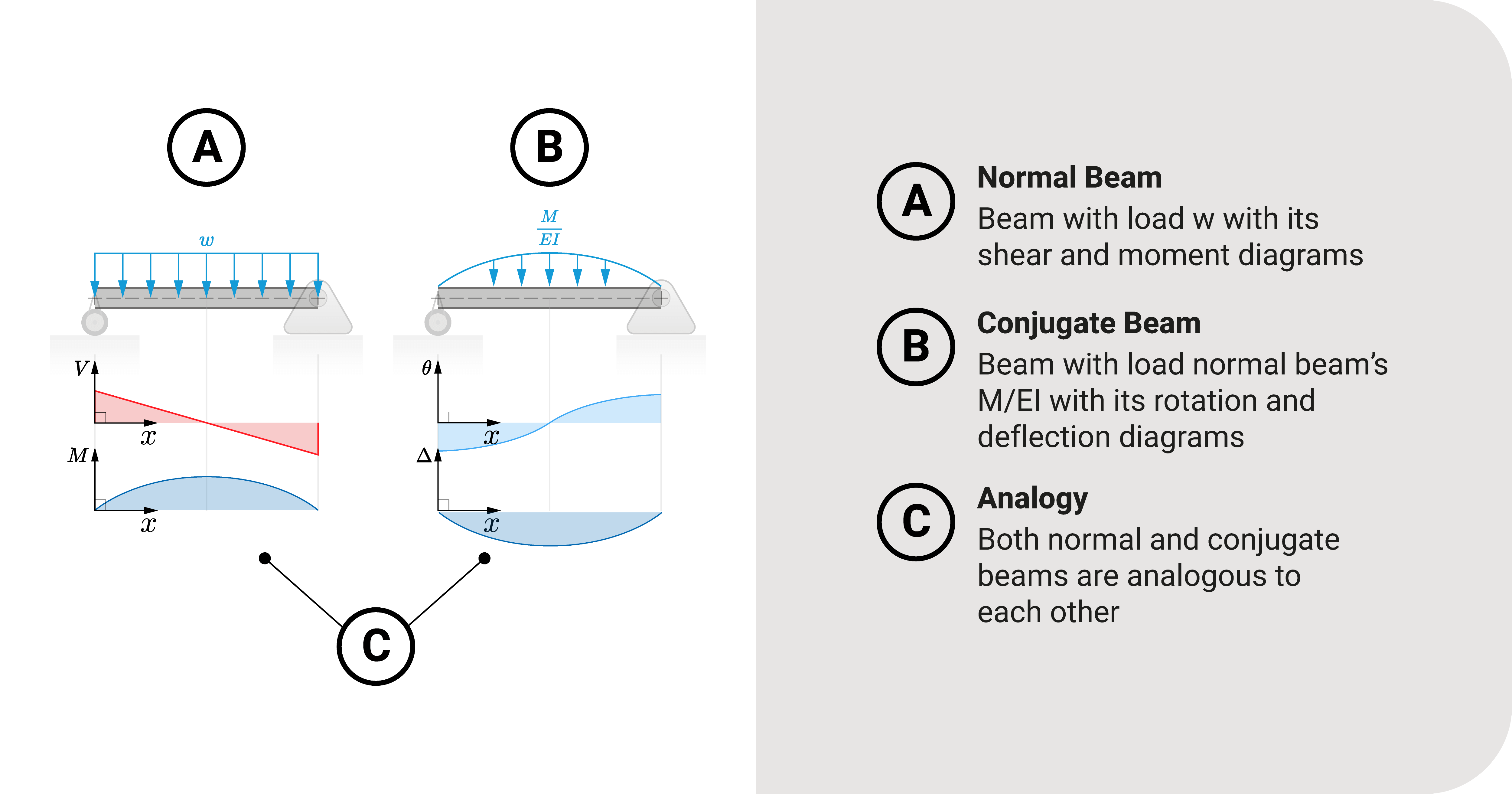
Let's start by investigating a simple beam \(AB\) loaded with a uniform distributed load \(w\).
Any Strength of Materials topic will tell you that there is a relationship between load, shear, and moment:
Load: \(\frac{d^2M}{dx^2}=w\space(load)\)
Shear: \(\frac{dM}{dx}=V\space(shear)\)
Moment: \(M=(moment)\)
A primary application of these equations is that you can model \(V\) and \(M\) without deriving the shear and moment equations per segment. For example, if we want to get the moment at \(B\) (assuming we know the moment at \(A\)), we get the area of the shear diagram from \(A\) to \(B\) and add it to the moment at \(A\).
The figure shows the whole shear and moment diagram of our beam example.
Moving on, we also have discussed the Bernoulli-Euler Beam Equation and how integrating it twice will lead us to solve for deflection components:
\(\frac{M}{EI}\): \(\frac{d^2\Delta}{dx^2}=\frac{M}{EI}\space(moment/EI)\)
Rotation: \(\frac{d\Delta}{dx}=\frac{\theta}{EI}\space(rotation)\)
Translation: \(\frac{\Delta}{EI}=(translation)\)
This set of relationships heavily implies that \(\frac{M}{EI}\), \(\theta\), and \(\Delta\) are connected.
If you make a comparison between these two sets of equations, you'll notice that there is parallelism:
- Load is similar to \(\frac{M}{EI}\).
- Shear is similar to the rotation.
- The moment is similar to deflection.
If there is an analogy between the two sets, we can adopt a similar solution, just like the first set. That is, solving for deflection is the same as finding the shear and moment of a beam. To do that, we create a structure similar to its counterpart called the conjugate beam.
Constructing the conjugate beam is straightforward:
- The length of the conjugate beam is similar to that of the actual beam.
- To maintain the analogy between the two sets of equations, we treat the \(\frac{M}{EI}\)-diagram as a fictional load applied to the conjugate beam.
- We must introduce artificial constraints for specific beams like overhangs and cantilevers (more at this post).
We shift our focus first on the conjugate beam theorems.
Key Idea: Conjugate Beam Theorems
How do we exactly solve for deflection using this method? To answer, let's discuss the method's two theorems based on our earlier analogies:
Theorem 1: Conjugate Shear is Real Rotation

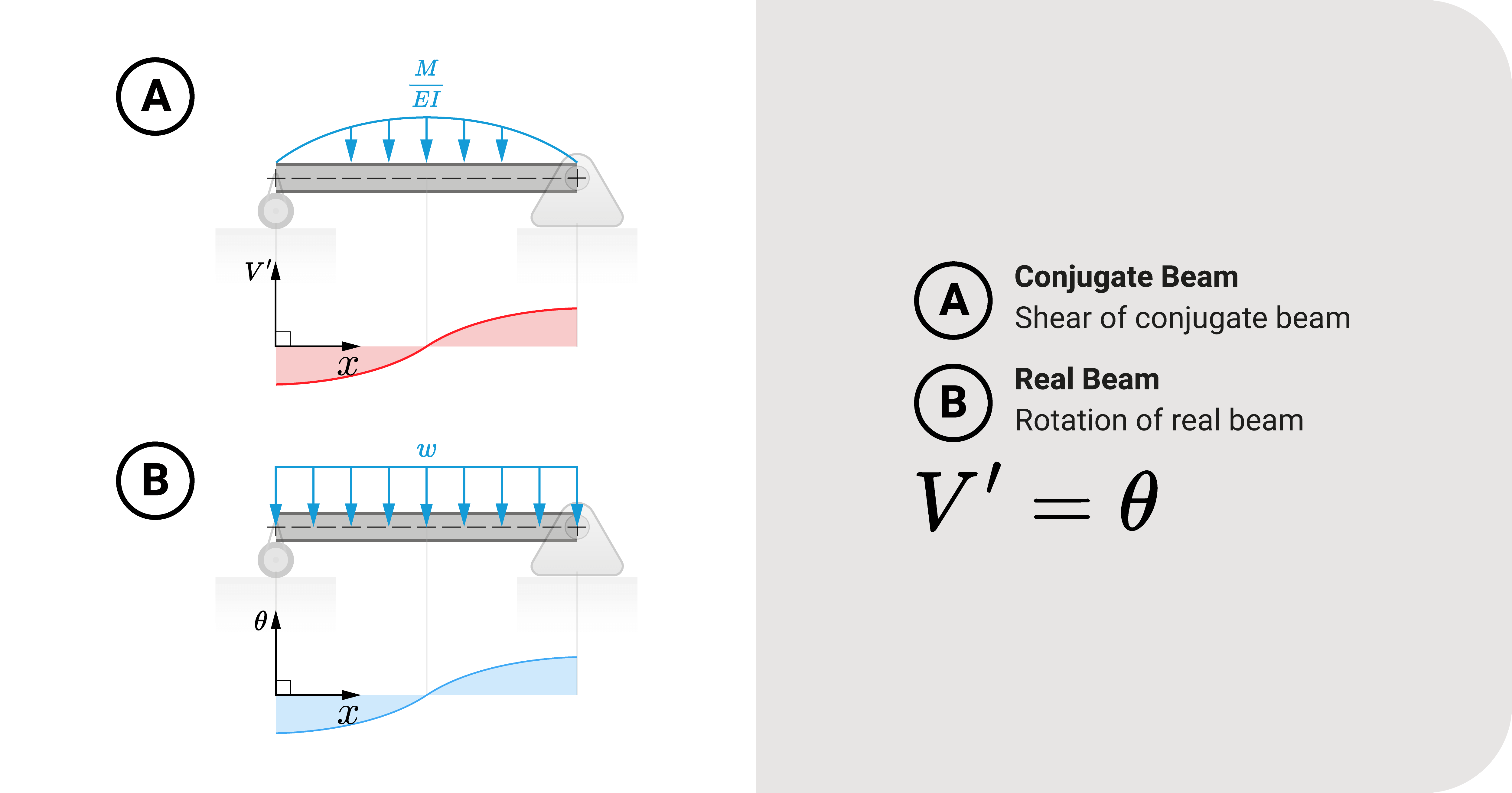
The first theorem deals with finding rotation \(\theta\) at a specific point. It states that: the fictional shear of the conjugate beam at any point is the rotation (slope) of the actual beam at said point.
\(V^{\prime}=\theta\)
Learn more about this theorem using this link.
Theorem 2: Conjugate Moment is Real Translation

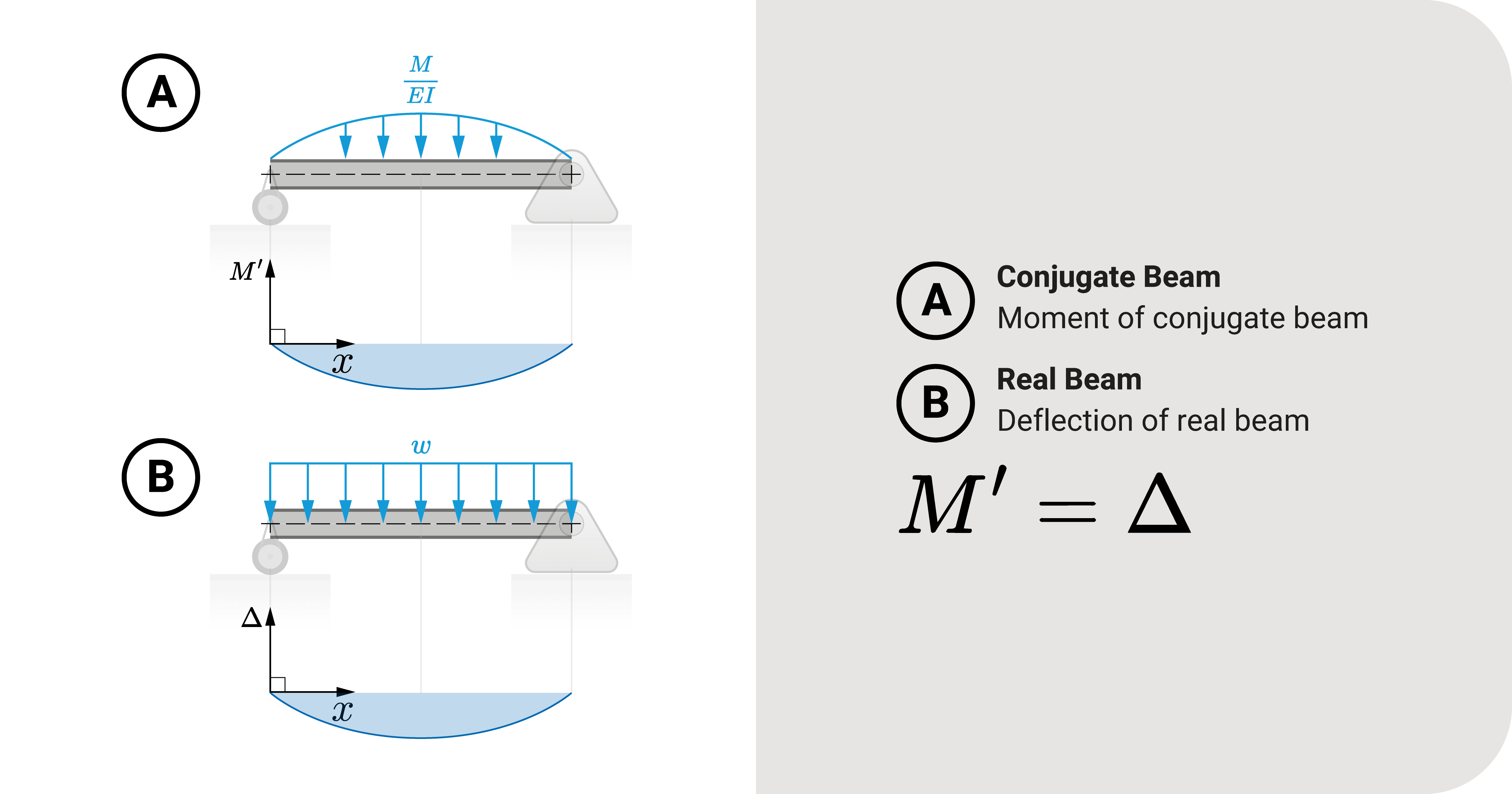
If the first theorem deals with rotation \(\theta\), then the second theorem deals with translation \(\Delta\). It states that: the fictional moment of the conjugate beam at any point is the translation (slope) of the actual beam at said point.
\(M^{\prime}=\Delta\)
Learn more about this theorem using this link.
Using the Conjugate Beam Method
The conjugate beam method is straightforward. We'll use an illustrative example to show how it works.
Summary
Let's summarize:
The conjugate beam method is an analytical procedure in which solving deflections is similar to finding a structure's shear and moment. It is an expansion of the area moment method.
It revolves around making an analogy between the actual beam, and its conjugate counterpart: (1) load is similar to \(\frac{M}{EI}\), (2) shear is similar to the rotation, and (3) the moment is similar to deflection.
Constructing the conjugate beam is straightforward: (1) The length of the conjugate beam is similar to that of the actual beam, (2) To maintain the analogy between the two sets of equations, we treat the \(\frac{M}{EI}\)-diagram as a fictional load applied to the conjugate beam, (3) We must introduce artificial constraints for specific beams like overhangs and cantilevers (more on this later).
Two theorems are needed to solve deflections using this method: (1) conjugate shear is actual rotation, and (2) conjugate moment is actual translation.
The first theorem states that: the fictional shear of the conjugate beam at any point is the rotation (slope) of the actual beam at said point.
The second theorem states that: The fictional moment of the conjugate beam at any point is the translation (slope) of the actual beam at said point.


